
Holiday Light Sequencer Circuit

However, if S2 is set to a position where all outputs are high or all are low (a rare occurrence), the sequence halts, and the outputs remain either fully on or off. In such a case, switching back to the original position for at least one pulse duration and then returning to the previous position is necessary. Additionally, S2 must be in its original position (pin 4 connected to pin 14) each time power is applied. This is essential because the data on pin 4 must be a logic 1 to initiate a sequence; otherwise, all outputs remain at logic 0, regardless of the clock pulses. Each output of the sequencing circuit connects to an MOC3010 optoisolator/coupler (U3 through U6), which consists of an infrared-emitting diode and an infrared-sensitive diac (triac driver or trigger) positioned closely together. When the infrared-emitting diode receives a logic 1, it activates, causing the diac to conduct. With the diac conducting, the triac activates, supplying power to any load connected to the corresponding AC socket. Consequently, the sequencing circuit and the 117-V AC outputs are optically isolated from one another. The sequencing circuit is powered by a 6.3-V miniature transformer. The output from the transformer is rectified using a four-diode bridge circuit, and the output is filtered by capacitor C1 (1000 µF electrolytic capacitor). Capacitor C3 is added at the supply pin of U2 to mitigate transients.
The circuit design utilizes a 555 timer as an astable multivibrator, generating a square wave output that serves as a clock signal for the flip-flops. The frequency of oscillation is determined by the values of R11 and the timing capacitor connected to the 555 timer. The 74C175 flip-flops are configured in a cascading manner, enabling the propagation of data through the series of flip-flops on each clock pulse. The ability to invert the input data via switch S2 introduces versatility, allowing for dynamic sequence generation based on the timing of the switching action.
The MOC3010 optoisolators play a crucial role in isolating the low-voltage control side of the circuit from the high-voltage AC loads being switched. The infrared-emitting diode inside the optoisolator activates the diac, which in turn triggers the triac, allowing for safe control of high-voltage devices without direct electrical connection. The design ensures that the sequencing circuit operates reliably, with power supplied through a miniature transformer and regulated by rectification and filtering components, providing stable operation even in the presence of transients. The inclusion of C3 serves to enhance the stability of the power supply to the flip-flops, ensuring consistent performance during operation. Integrated circuit Ul (a 555 oscillator/timer) is wired as a conventional pulse generator. The frequency of the pulse generator is controlled by potentiometer Rll. Resistor R2 puts areasonable limit on the highest speed attainable. The output of the pulse generator is fed to the common clock input of U2, a 74C175 quad D-type flip-flop. Each flip-flop is configured so that its Q output is coupled to the D input of the subsequent flip-flop.
Information on the D input of each flip-flop is transferred to the Q (and Q) outputs on the leading edge of each clock pulse. Switch S2 allows you to invert the information on the D input of the first flip-flop at any time during the cycle.
This allows you to create a number of different sequences, which are determined by the state of the CQ output at the time of the switching. However, if S2 is switched to position while all outputs are high or all are low (which seldom occurs), the sequence stops and the outputs remain either all on or all off. If that happens, you only need to switch back to position A for at least one pulse duration, then back to position again.
Likewise, S2 should be in position A (pin 4 connected to pin 14) each time the power is turned on. This is because the data on pin 4 must be a logic 1 in order to start a sequence; otherwise all outputs remain at logic 0, regardless of the clock pulses. Each output of the sequencing circuit is connected to an MOC3010 optoisolator/coupler (U3 through U6), which contains an infrared-emitting diode with an infrared-sensitive diac (triac driver or trigger) in close proximity.
The diac triggers the triac, which carries the 117-volts ac. Each time that the infrared- emitting diode receives a logic 1, it turns on and causes the diac to conduct. With the optoisolator/coupler`s internal diac conducting, the triac turns on, and power is supplied to whatever load is plugged into the corresponding ac socket.
So, the sequencing circuit and the 117-V ac outputs are optically coupled and are effectively isolated from each other. Power for the sequencing circuit is provided by a 6.3-V miniature transformer. The output of the transformer is rectified by a four-diode bridge circuit, the output of which is filtered by CI (1000- electrolytic capacitor).
Capacitor C3 is added at the supply pin of IJ2 to suppress transients.
Related Circuits
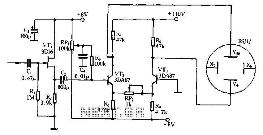
Application of the differential amplifier circuit in a simple small oscilloscope. The differential amplifier circuit is a crucial component in the design of a simple small oscilloscope. This circuit is designed to amplify the difference between two input voltage signals...
This circuit gives a low-level output when sufficient lighting is present, functioning as a light detector. It can issue a command to turn on lights when darkness falls. Its output is compatible with TTL levels, providing a low logic...
Cook in advance to open the door with a coal stove; before using the fire, it should be strong. This is an automatic door opening device that can automatically open the door before the regular homeowner, eliminating the need...
Dark Activated Switch or Porch Light Switch. This circuit activates a relay when the light level drops below a preset threshold. The light sensitivity can be adjusted using variable resistor VR1, and the relay contacts can control an external...
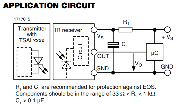
There is an interest in starting an introductory electronics project using an infrared (IR) sensor, but there is some confusion regarding the application circuit provided in the datasheet. The recommended resistor value is significantly lower than the calculated value....
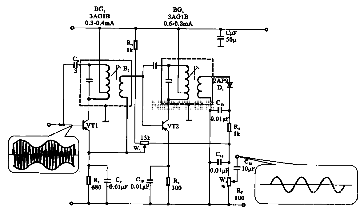
The demodulation and detection circuit is a radio AM intermediate frequency (IF) signal amplifier that performs two-stage detection using diode Dr. It extracts the audio signal from the IF carrier detection and subsequently sends it to the power amplifier...