
10w audio amplifier circuit
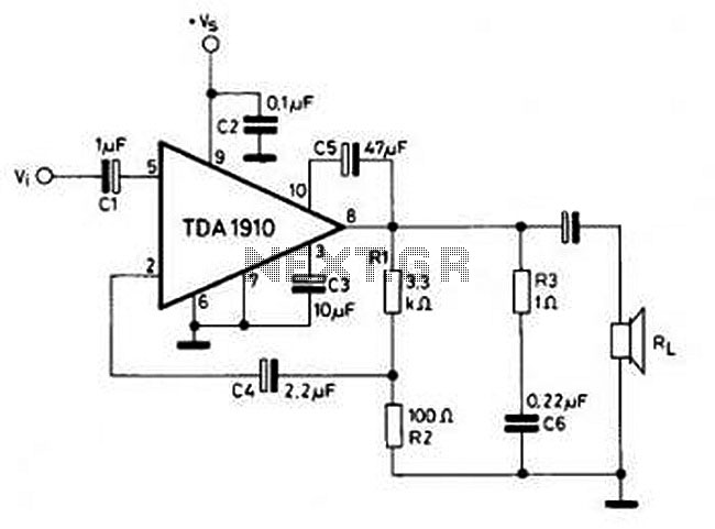
The circuit utilizes the TDA1910 integrated circuit, which is designed for audio amplification applications. The TDA1910 is known for its low noise characteristics, making it ideal for projects where sound fidelity is important, even at lower power levels. The circuit typically includes basic components such as resistors, capacitors, and a power supply to facilitate the amplification process.
The input stage of the circuit receives audio signals, which are then processed by the TDA1910. The gain can be adjusted through external resistors, allowing for customization based on the desired output level. It is essential to ensure that the power supply voltage meets the specifications of the TDA1910 to avoid distortion or damage.
Output capacitors may be employed to block any DC component from the amplified signal, ensuring that only the AC audio signal is transmitted to the speakers. Additionally, the circuit may include a heat sink for the TDA1910 to dissipate heat generated during operation, especially when the circuit is driven at higher volumes.
This circuit is particularly well-suited for educational purposes, as it provides a practical understanding of audio amplification principles, component selection, and circuit design. Students can experiment with different configurations, such as varying the input signal or adjusting the gain, to observe the effects on audio output. Overall, this project not only serves as a functional audio amplifier but also enhances learning in electronics and audio engineering.Simple and cheap, that`s the advantage of this circuit. Although the output power is not high but audio quality is good, because TDA1910 has a very low noise feature. This circuit suitable for use as a student project. 🔗 External reference
Related Circuits
The following circuit illustrates the connection of the Devantech SRF04 Ultrasonic Sensor to the SV203 powered PPRK Circuit Diagram. This circuit is based on the Devantech SRF04 sensor and features a minimum initiation time of 10 milliseconds for the...
The pulser is designed to switch the mains voltage on and off at intervals ranging from just under one second to up to 10 minutes. This functionality is particularly useful for testing mains-operated equipment over extended periods or for...
The circuit is a simple op-amp but with two diodes (the transistor b-e junctions in the feedback to split the feedback for positive and negative outputs. On positive output from the stepper coil the top transistor turns on, on...
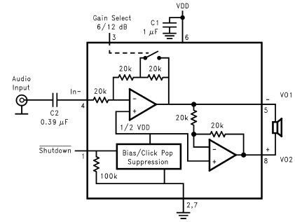
The LM4096 audio amplifier circuit diagram represents a straightforward audio amplifier capable of delivering a maximum output power of 1 watt, utilizing a minimal number of external electronic components. The LM4906, an audio power amplifier, is specifically engineered for...

FAN7710 Ballast Control circuit design for Compact Fluorescent Lamps electronic project. The FAN7710 is a specialized integrated circuit designed for the control of ballast systems in compact fluorescent lamps (CFLs). This circuit typically operates in a high-frequency range, facilitating efficient...
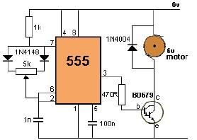
This project utilizes a 555 timer to control the speed of a 6-volt DC motor. Speed adjustment is achieved by rotating a 50 kΩ potentiometer either to the left or right. The circuit employs a 555 timer configured in astable...