
raspberry pi gpio pin electrical specifications

The GPIO pins on a Raspberry Pi are versatile components essential for various electronic projects and applications. Each GPIO pin can be configured as either an input or an output, allowing for a wide range of functionalities. When configured as an input, the GPIO pins can read digital signals, which may come from sensors, switches, or other digital devices. This capability enables the Raspberry Pi to interact with the physical environment, making it suitable for automation, robotics, and IoT applications.
As output pins, the GPIO can be used to control devices such as LEDs, relays, and other small electronic components. The GPIO pins typically output a voltage of 3.3V, which is sufficient for driving low-power devices. However, due to the limited current output—usually around 16-20 mA per pin—it is crucial to ensure that the connected devices do not exceed this current limit to avoid damaging the Raspberry Pi.
For projects requiring higher current levels, it is advisable to use transistors or relays as intermediaries. This approach allows the GPIO pin to control the transistor or relay, which can then switch larger loads without putting undue stress on the Raspberry Pi's GPIO pins. Additionally, proper circuit design should include current-limiting resistors when driving LEDs to prevent excessive current flow.
In summary, the GPIO pins on the Raspberry Pi are a powerful feature that enables users to interface with a variety of electronic components, facilitating the development of innovative projects and solutions in the field of electronics and computing.The Raspberry Pi provides general purpose digital input/output pins (called GPIO pins) that you can use for reading digital logic signals or for outputting digital logic levels. The outputs do not have much current capability, but you can drive LEDs or.. 🔗 External reference
Related Circuits

For the DIY Motion Platform III, the electrical motion drive was expanded to three channels. The small signal concept remained unchanged, but the MOSFET half-bridge was modified to a full bridge (H-bridge). The DAC converter was upgraded to a...
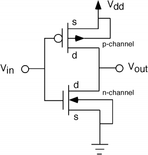
The fundamental issue presented is the perception that logic gates in a circuit seem to generate power from nothing, which contradicts the principles of physics. For instance, consider two NOT gates connected in series. It appears that the first...
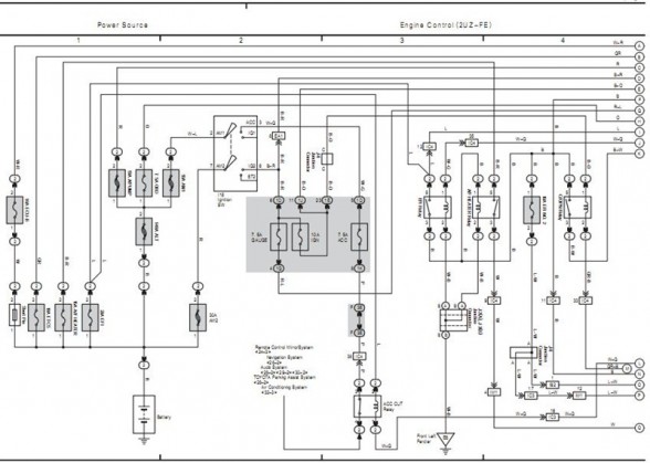
The following circuit illustrates the electrical circuit diagram for the 2006 Toyota 4Runner. It includes specifications related to the Toyota vehicle and details on safety features. The electrical circuit diagram of the 2006 Toyota 4Runner serves as a comprehensive representation...
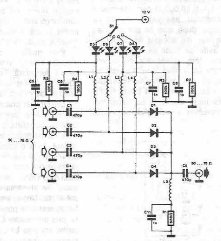
This antenna selector circuit diagram utilizes PIN diodes, which address the drawbacks of mechanical switches, particularly in high-frequency current applications. PIN diodes are well-suited for this purpose due to their linear resistance characteristics across a wide range of current...
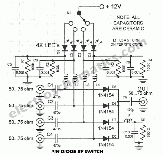
This PIN diode RF switch is an ideal antenna switch for VHF and UHF applications. It operates with PIN diodes, which are specialized high-frequency switching diodes. The PIN diode RF switch is designed to efficiently route RF signals in the...
When the infrared receiver tube PH302 receives a signal from the remote control, the CX20106A selected frequency amplifier outputs a low-frequency signal. The low-level signal charges capacitor C through diodes D and R, causing the negative side potential of...