
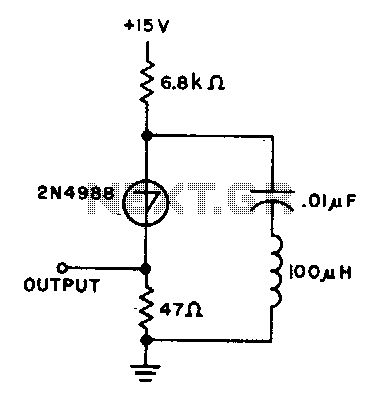
RC Audio Oscillator

The audio oscillator circuit operates on the principle of generating a periodic waveform, typically a sine or square wave, which is essential for various audio applications. The core of the oscillator is often based on a feedback loop that includes active components such as operational amplifiers or transistors, alongside passive components like resistors and capacitors. In this design, the frequency of oscillation is predominantly influenced by the values of the capacitors and resistors used in the circuit.
The 0.01 µF capacitors play a crucial role in determining the timing characteristics of the oscillator. The frequency \( f \) of the oscillator can be approximated using the formula:
\[
f = \frac{1}{2 \pi R C}
\]
where \( R \) is the resistance in ohms and \( C \) is the capacitance in farads. In this design, the 5.6 kΩ resistors work in tandem with the capacitors to set the desired oscillation frequency around 1 kHz. Adjusting the capacitance by replacing the 0.01 µF capacitors with different values allows for fine-tuning of the output frequency, enabling the generation of various audio tones as needed for testing purposes.
The inclusion of an 8-volt regulator is essential for stabilizing the power supply to the oscillator, ensuring consistent performance across different operating conditions. While the specific regulator design is left to the user's discretion, it is advisable to select a low-dropout regulator (LDO) to maintain efficiency, especially if the oscillator is powered from a battery source.
Overall, this audio oscillator circuit is a practical tool for audio testing and development, providing flexibility in tone generation and stability in operation. The schematic serves as a foundational guide, allowing for customization and adaptation to specific testing requirements in audio electronics.Here is the design of an audio oscillator that runs at approximately 1 KHz. I don`t remember where I got this circuit, probably from EMFRD, since Wes`s book is a treasure trove of useful circuits. This handy oscillator can be used as a source of audio for testing out audio stages in receivers and the like, or as a stable signal source for testing
microphone circuits in transmitter. Aschematic of the audio oscillator. What is not shown is the 8-volt regulator circuitry that is part of the finished module. Just use your favorite part and circuitry there, it isn`t critical at all. This view shows a bit more detail of the 0. 01 uF capacitors, the red-orange units in the foreground, used along with the 5. 6K resistors to set the frequency of oscillation. These capacitors can be changed for a higher or lower audio tone. 🔗 External reference
Related Circuits
A transformer with two separate 12V secondary windings is required for the power supply. If the transformer does not have a third separate winding, the supply input of the S/PDIF decoder must be connected in parallel to the positive...
The capacitor charges until the switching voltage is reached. When the switch (SUS) is activated, the inductor causes the current to oscillate. When the current through the switch drops below the holding current, the device turns off, and the...
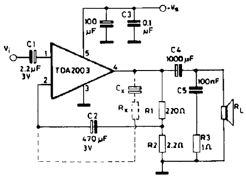
The TDA2003 offers enhanced performance while retaining the same pin configuration as the TDA2002. It maintains the advantageous features of the TDA2002, including a minimal number of external components, ease of assembly, and savings in both space and cost....
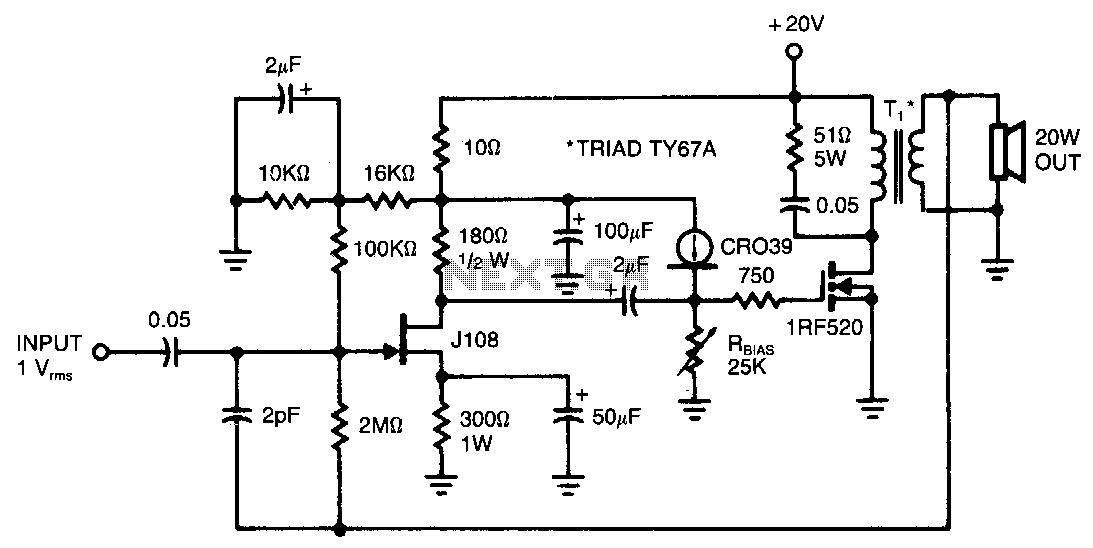
This amplifier provides 20 W of power to an 8-ohm load utilizing a single IRF520 transistor driving a transformer-coupled output stage. The design resembles the audio output stages commonly found in many low-cost radios and phonographs. Distortion remains below...
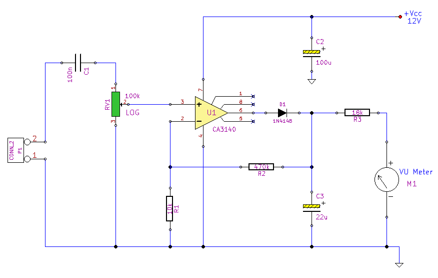
This simple circuit, designed with a minimal component count, indicates peak audio response on an analog meter, similar to a tape recorder's meter. It employs an operational amplifier configured as a non-inverting amplifier, with the addition of a diode...
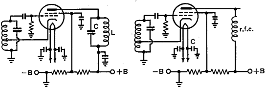
One of the significant challenges in designing vacuum-tube oscillators is maintaining a constant frequency despite mechanical vibrations, temperature fluctuations, voltage variations in the supply lines, and changes in the load power drawn from the circuit. The effects of variable...