
RC Charger

The circuit described involves a battery charging system that utilizes a transformer, diodes, a variable resistor, and an L200 voltage regulator. The primary function of this circuit is to provide a regulated charging voltage to a battery while ensuring safe operating conditions for the components involved.
The charge current (I) is determined by the equation I = 0.45V/R2, where R2 is a resistor used to limit the current flowing into the battery. The power dissipation across R2 can be calculated using the formula (0.45 * 0.45) / R2, which indicates that the resistor must be rated to handle the calculated power without overheating.
To achieve the desired output voltage of 13.8V for charging, R5 is employed as an adjustable resistor. It is crucial to adjust R5 while the battery is not connected to prevent damage or incorrect charging conditions.
The diodes D1 through D4 and D6 are selected based on the charge current requirements. For charge currents less than 1A, diodes such as the 1N4001 through 1N4007 are suitable. For higher charge currents, specifically up to 2A, the 1N5401 diode is recommended. D5, which may be used for additional protection or regulation, can be either a 1N4184 or a 1N4001, depending on the specific circuit design and requirements.
The transformer is specified to provide a maximum output of 15V at 2A, which is adequate for the intended charging application. The transformer steps down the voltage from the mains supply to a suitable level for the charging circuit.
The L200 voltage regulator is a critical component in this design, providing a stable output voltage and current regulation. Adequate cooling for the L200 is necessary to ensure reliable operation and prevent thermal shutdown. This may involve using a heatsink or other cooling methods to maintain optimal operating temperatures.
Overall, this circuit design provides a robust solution for battery charging applications, with careful consideration given to component selection, current limiting, and thermal management.Charge current: I=0,45V/R2 Power-dissipation by R2: (0,45 * 0,45 / R2) ! Please adjust 13,8V by R5 without connected battery. D1 - D4, D6 : charge-current less than 1A: 1N4001 (up to 1N4007) charge-current up to 2A: 1N5401 D5: 1N4184 , 1N4001. Transformer: 15 V max 2 A The L200 must be cooled. 🔗 External reference
Related Circuits
Lithium Ion batteries pack a lot of power by weight compared to other types. There are 2 things that need to be handled differently than nicad or NiMH. They cannot be used as a direct substitute (even if they...
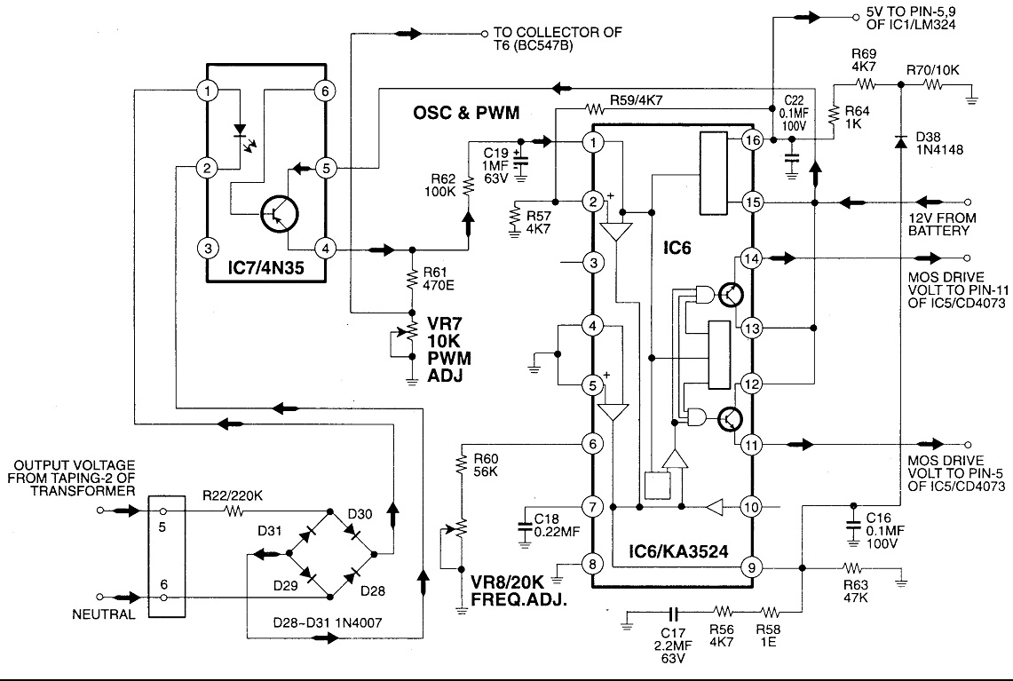
Circuit No. 1 (Oscillator Circuit and Feedback Circuit) Circuit No. 2 (MOS Driver Circuit) Final Product: - Operation of Circuit No. 1 (Oscillator Circuit and Feedback Circuit) This inverter utilizes Pulse Width Modulation (PWM) technology. The working principle of...
All car batteries require a 12V battery charger, which also applies to marine, RV, and power sports batteries. The high-efficiency lead-acid batteries available today necessitate more effective charging techniques. The battery charger is a crucial tool for prolonging battery...
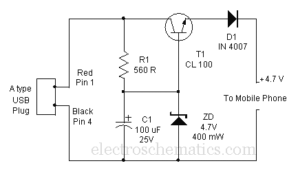
Comprehensive information about a USB cellphone charger circuit is available for learning and downloading online. The USB cellphone charger circuit is designed to convert AC mains voltage into a stable DC voltage suitable for charging mobile devices. This circuit typically...
This is a charger circuit designed for both NiCd and NiMh batteries. An old commercial handheld transceiver powered by a 12-volt NiCd battery pack (comprising 10 button cells, each with a capacity of 280mAh) was acquired. The battery, which...
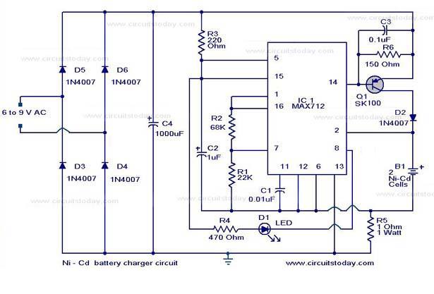
The following circuit illustrates a super fast Ni-Cd battery charger. It is based on the IC MAX 712 and is designed to charge a Ni-Cd battery at a rate of 300 mA. The circuit utilizes the MAX 712 integrated circuit,...