
Turntable Rumble Filter
The active high-pass Chebyshev filter designed for record players addresses the common issues of rumble and low-frequency interference. This filter operates with a 0.1-dB ripple characteristic and a cut-off frequency of 18 Hz, which effectively mitigates unwanted noise while preserving audio fidelity. The Chebyshev filter type, while not traditionally favored for audio applications, offers advantages in terms of sharper roll-off characteristics compared to other filter types, such as Butterworth filters, which have a more gradual slope.
The filter's design ensures that frequencies below 10 Hz are attenuated by more than 35 dB, contributing to a cleaner audio output. The gradual phase shift within the pass band is engineered to be inaudible, thereby maintaining the integrity of the sound reproduction. In stereo configurations, it is critical that the filters in both channels maintain identical characteristics to prevent phase discrepancies that could affect the listening experience, particularly in the mid-range frequencies.
Capacitors C1 through C5 are pivotal in achieving the desired filter characteristics. They should be selected with a tolerance of 1%, ensuring that slight variations in capacitance do not significantly alter the cut-off frequency. Capacitors can be paired for symmetry across channels, allowing for consistent performance. The schematic will provide theoretical resistor values, while practical implementations can utilize 5% metal-film resistors from the E12 series, which have been found to perform satisfactorily without extensive sorting.
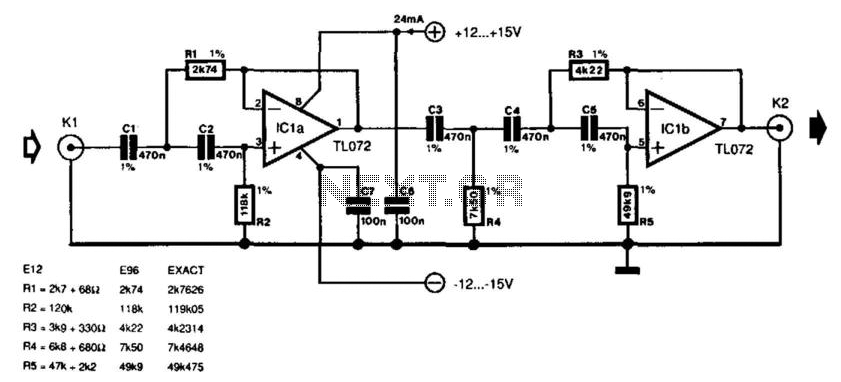
The circuit draws approximately 4 mA of current, primarily through the operational amplifier, which also defines the high cut-off frequency, approximately 3 MHz. Attention should be given to any coupling capacitors in the signal source, as these may interact with capacitor C1, potentially altering the frequency response. If the coupling capacitor's value exceeds 47 μF, it is unlikely to impact performance; however, if it is less than this threshold, removal is advisable, allowing capacitor C1 to fulfill its intended role in the filter circuit. Many record players unfortunately exhibit two undesired side effects: rumble (noise caused by the motor and the turntable) and other low-frequency spurious signals. The active high-pass Chebyshev filter presented here was designed to suppress those noises. The filter has a 0.1-dB ripple characteristic and a cut-off point of 18 Hz. The choice of a Chebyshev filter might not seem optimum for audio purposes, but because of its 0.1-dB ripple in the pass band it behaves very much like a Butterworth type.
Its advantage is that the response has steeper skirts (which are calculated curves). Frequencies below 10 Hz are attenuated by more than 35 dB. The phase behavior in the pass band shows a gradual shift so that its effect on the reproduced sound is inaudible. If the filter is used in a stereo installation, the characteristics of both filters must be identical or nearly so.
Phase differences between channels can be heard—perhaps not so much at lower frequencies, but certainly in the mid ranges. To ensure identity and also to obtain the desired characteristics, capacitors CI through C5 must be selected carefully.
It does not matter much whether their value is 467 or 473 pF; this difference only causes a slight shift of the cut-off point. However, they must be identical within that 1% tolerance. For symmetry of channels, the capacitors can be paired and then used in either channel at the corresponding position.
The diagram shows theoretical values for the resistors: their practical values are given in the table. The prototype was constructed with 5% metal-film types from the E12 series and these were used without sorting.
Their tolerance was perfectly acceptable in practice. The current drawn by the circuit is purely that through the op amp and it amounts to about 4 mA. The high cut-off point is also determined by the op amp and it lies at about 3 MHz. The only problem that cannot be foreseen is a possible coupling capacitor in the signal source. That component will be in series with CI and this might adversely affect the frequency response. However, if its value is greater than 47 Â¥, it will have little if any effect; if it is below that value, it is best removed; CI will assume its function. 🔗 External reference
Related Circuits
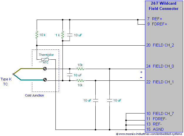
Filtering thermocouple wires ensures highly accurate temperature measurement by preventing noise pickup, decoupling thermocouple signals, and reducing measurement errors. A thermocouple noise filter circuit is effective in minimizing these errors. The implementation of a thermocouple noise filter circuit is essential...
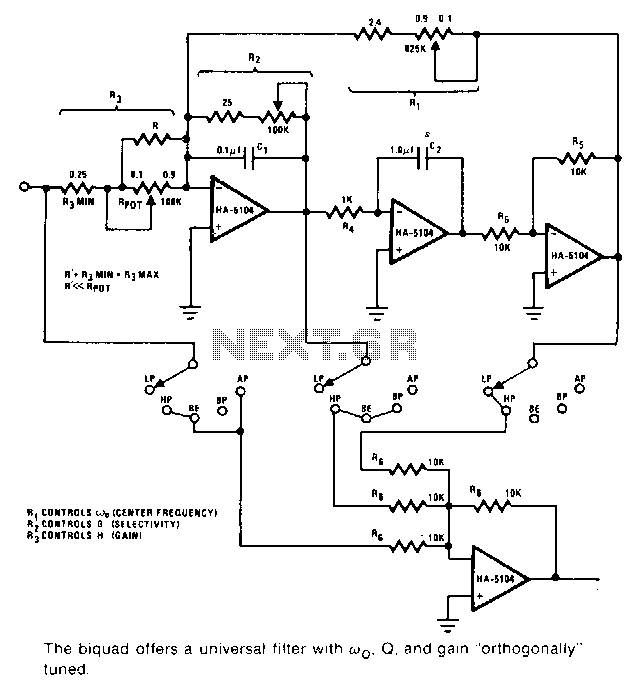
This universal filter provides low-pass, high-pass, bandpass, band elimination, and all-pass functions. The Biquad consists of two successive integration stages followed by an inverting stage. The entire system features a feedback loop from the front to the back, primarily...
On this page three adjustable notch filters configurations are shown. They can be used in your small pre-amp or amplifier project to filter out any HUM at 50 Hz (European) or 60Hz. By substituting the capacitors values in the...
The schematic shown does not need any power supply because it is a simple low frequency passive filter. It could be useful if you want to drive an extra subwoofer from your stereo system. The circuit filters the frequency...
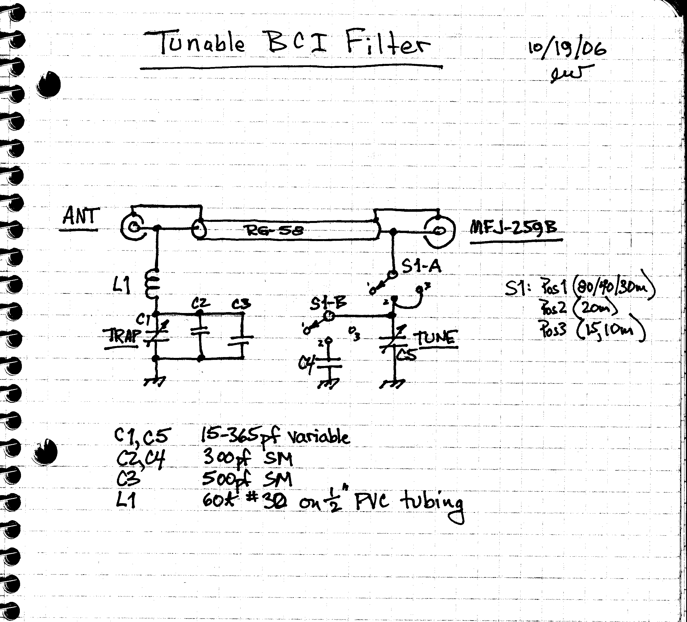
The design involves creating an AM broadcast signal eliminator. An undesired AM broadcast signal is directed to ground using a series resonant circuit composed of inductor L1 and capacitors C1, C2, and C3. At high frequencies, this series circuit...
At first glance, this circuit appears to be quite complex; however, it can be segmented into high-pass and low-pass filter sections, followed by a summing amplifier with a gain of approximately 20 times. The supply rail voltage is +/-...