
reading electricity meter ir impulses

The circuit involves a phototransistor that detects infrared light emitted by the electricity meter. The phototransistor's output is connected to an Arduino microcontroller, specifically to pin 2, which is configured to receive digital signals. The 10k resistor serves as a pull-up resistor, but concerns arise regarding its value and the overall biasing of the phototransistor. It is crucial to ensure that the resistor connects to the +5V supply to properly bias the phototransistor, allowing it to switch states effectively when it detects an infrared pulse from the meter.
In this setup, the phototransistor operates in a mode where it conducts current when exposed to infrared light, resulting in a change in voltage at pin 2 of the Arduino. The Arduino's pin mode must be set to INPUT to detect these changes. If the phototransistor is not sensitive enough or if the pulse width from the electricity meter is too short, the Arduino may not register the signal, leading to the observed issue.
To analyze the output from the phototransistor, the use of an oscilloscope is recommended. This tool can visualize the signal waveform, providing insights into the frequency and duration of the pulses emitted by the electricity meter. Adjustments to the code may be necessary to ensure that the interrupt service routine correctly handles the short pulse from the meter, allowing for accurate detection and response.
In summary, the circuit's effectiveness relies on the proper configuration of the phototransistor, resistor values, and Arduino code. Ensuring that the phototransistor is adequately biased and that the microcontroller is set up to handle the incoming signals will enhance the likelihood of successfully reading the infrared impulses from the electricity meter.Yesterday I was triyng to read the infrared impulses from my electricity meter. The phototransistor I`m using, can see the IR from all the remotes in the house. but doesn`t read the blink from the electricity meter. I can see the IR blink of the meter with any camera, is bright and powerful enough. I wonder why the phototransistor doesn`t see it You see the remotes since they put out a long train of pulses, the meter is apparently only putting out one short pulse. So either the frequency response or the sensitivity of the phototransistor is too low. Do you have an oscilloscope that you can view the signal with You see the remotes since they put out a long train of pulses, the meter is apparently only putting out one short pulse.
So either the frequency response or the sensitivity of the phototransistor is too low. Do you have an oscilloscope that you can view the signal with But I don`t really understand your circuit. You have a 10k resistor going from the PT to pin 2 of the Arduino. So how does the Arduino bias the PT What is the mode of pin 2 It would seem that you would want the resistor going to +5V and the junction of the PT and the resistor going to pin 2.
Just saw in Arduino`s documentation that I actually have a problem in my code. I`m trying to turn the status LED on and off there. and that`s not possible with a delay (just learned that delay doesn`t work in the function called by attachInterrupt: ). You were right, the impulse probably is too short and I don`t have a blink and with remote control works because they put out a long train of pulses.
I should modify the code to: But I don`t really understand your circuit. You have a 10k resistor going from the PT to pin 2 of the Arduino. So how does the Arduino bias the PT What is the mode of pin 2 It would seem that you would want the resistor going to +5V and the junction of the PT and the resistor going to pin 2. Yes, I asked from the start about the 10k resistor. There must be a pull up resistor on the Arduino. It is probably 100k. To get speed I think the pull up to +5V resister must be much smaller than 100k. There are some unknowns here. 🔗 External reference
Related Circuits
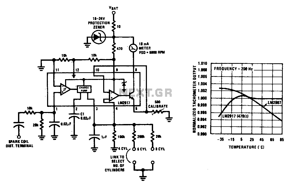
This tachometer can be configured for any number of cylinders by connecting the appropriate timing resistor as illustrated. A 500-ohm trim resistor can be utilized for final calibration. Additionally, a protection circuit consisting of a 10-ohm resistor and a...

This circuit is designed for precise centigrade temperature measurement. It includes a transmitter section that converts the sensor's output voltage, which is proportional to the measured temperature, into frequency. The output frequency bursts are transmitted through the mains supply...

The circuit presented is designed to prevent burning one's tongue by monitoring the temperature of coffee. It consists of a voltage regulator, a temperature-to-voltage converter, a comparator, and two LEDs. In general, the circuit operates as follows: if the...

This temperature meter utilizes the precision micro power centigrade sensor IC LM35. The output voltage of the IC is linearly proportional to 10 mV per degree centigrade. The LM35 temperature sensor is a versatile and widely used device in electronic...
A milliamp meter can be used as a volt meter by adding a series resistance. The resistance needed is the full scale voltage reading divided by the full scale current of the meter movement. So, if you have a...
This project is also an essential part of the expandable analyser to be published soon or perhaps eventually, and one meter circuit is used for each frequency band. There are many other uses for a simple LED VU meter....