
Real Time Clock Using AT89C4051

The circuit design involves the AT89C4051 microcontroller, which serves as the central processing unit for managing the LCD display and user input. The LCD operates in 4-bit mode, utilizing Port 1 of the microcontroller to transmit data to the display. Pins 7 through 14 of the LCD are connected to the corresponding pins of Port 1, allowing for the display of alphanumeric characters. The first line of the LCD is configured to show the current "DAY" and "DATE," while the second line is reserved for displaying "TIME" along with an AM/PM indicator, providing a clear and user-friendly interface for time management.
Port 3 of the AT89C4051 is dedicated to clock settings, facilitating user interaction through three switches. Switch 3 is specifically allocated for selecting which parameter (DAY, DATE, or TIME) is to be modified. The other two switches, designated as switches 1 and 2, are responsible for incrementing or decrementing the value of the selected parameter. This arrangement allows for intuitive adjustment of the clock settings.
The programming aspect of the project is executed in C, utilizing the Keil C compiler for development and compilation. Users can access the complete project files, including the source code, schematic diagrams, and HEX file, which can be directly programmed onto the microcontroller. This flexibility ensures that users can replicate the project without necessitating a cross-compiler.
In terms of component selection, should there be any issues with sourcing the AT89C4051 microcontroller, alternatives such as the AT89C51 or AT89C52 can be employed. It is crucial, however, to ensure that the pin assignments for the LCD and switches remain consistent with those outlined in both the C code and schematic, thereby maintaining the integrity of the circuit's functionality.Port 1 of the controller (AT89C4051) is used as the data lines for the LCD (starting from pin 7- pin14 of LCD). here i am using a 16 x 2 lines LCD display. In the first line, I`ll display "DAY" and "DATE", in the second line, i am displaying "TIME" with am/pm.
Port 3 is used for the clock setting and it also provides the necessary control signals for the LCD. As shown in the diagram, switch3 will be used to select the parameter which need to be changed, switch 1 and 2, are used to increase or decrease the selected parameter value. The source code for the project is written in C-language, and compiled using Keil C compiler, you can download the c-code, schematic, and if you don`t have a cross compiler then you can directly burn the HEX file on to your chip, clock.
zip. NOTE: If you think that there is a problem in the availability of the chip mentioned in the schematic, then you can also use AT89C51/AT89C52, make sure that you are using the same port for LCD and switches which are there in the C-file or in the schematic. 🔗 External reference
Related Circuits

The duration for which the circuit remains active is determined by the time required for the stored electrical current to leak back into the circuit, which keeps the transistor and the entire circuit energized. A resistor is present that...
This timer is designed to automatically switch off a portable radio after a set period, allowing users to relax without worrying about battery drain. Resistor R1 and capacitor C1 create a long time constant. When switch P2 is momentarily...
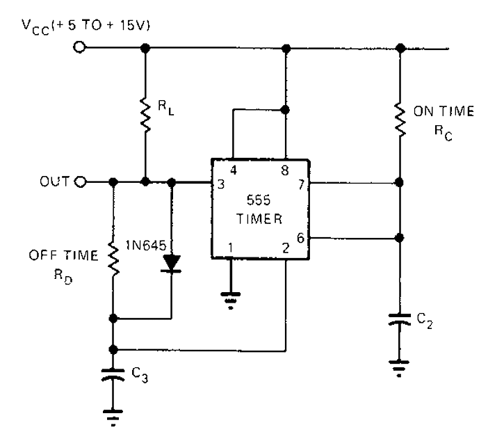
The 555 timer circuit has unsteady open and closing times that are independent of one another. One time constant is given by 1.1RcC2, while another time constant is defined as 1.1RcC3. The free-running period is the sum of these...
This device is a simple timer, allowing to keep on the headlights of your vehicle for about 1min. and 30sec., e.g. when accessing some dark place, without the necessity of coming back to switch-off the lights. The circuit design for...

Many times, code has been written for UART communication, but testing was hindered by the absence of a serial port on the laptop. A USB to serial port converter was purchased, but it did not function as expected. Frustration...
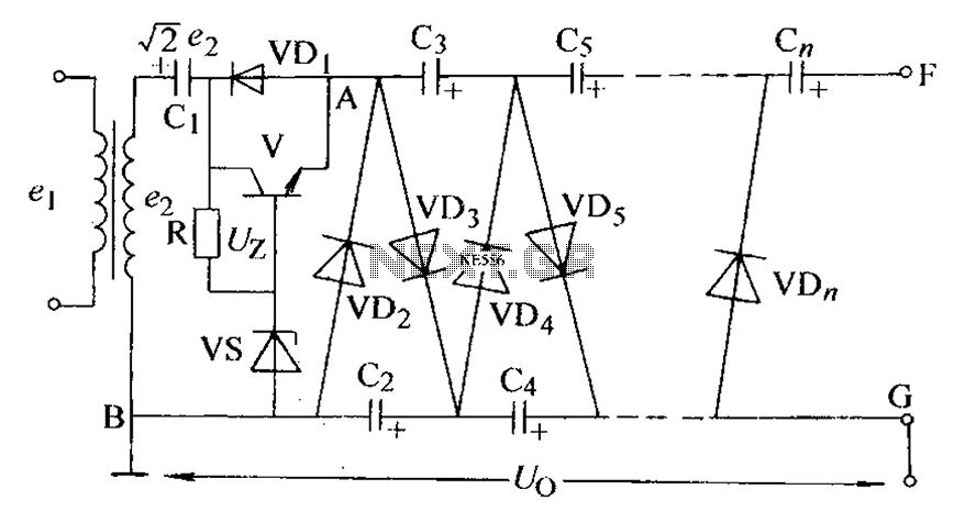
The circuit is an adjustable output voltage regulator type rectifier. It allows for obtaining peak voltage at odd multiples when the output voltage is taken from the circuit feedback (FB). Additionally, the lower point of the capacitor (CB) can...