
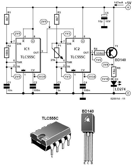
The Time Delay Circuit

The described circuit operates on the principle of energy storage and controlled discharge through a capacitor and resistor configuration. The capacitor serves as a temporary energy reservoir, storing electrical energy when the circuit is powered. The resistor is crucial in managing the discharge rate of the capacitor; its resistance value directly influences how quickly the stored energy is released back into the circuit.
In practical applications, this setup is commonly utilized in cold starting circuits, such as those found in automotive ignition systems or other applications requiring a brief surge of power. When the circuit is initially powered, the capacitor charges up to a certain voltage level. The transistor, acting as a switch, remains in the 'on' state as long as the voltage across the capacitor is above a certain threshold.
Adjusting the resistor value offers a straightforward method for tuning the circuit's performance. A higher resistance value increases the time constant of the RC (resistor-capacitor) circuit, effectively extending the time the transistor remains activated. This is particularly beneficial in applications where a longer duration of operation is necessary. On the other hand, a lower resistance value decreases the time constant, allowing for faster discharge and quicker deactivation of the circuit, which may be desirable in scenarios requiring rapid cycling or energy conservation.
In conclusion, the interplay between the resistor and capacitor is fundamental to the circuit's operation, with careful selection of component values enabling precise control over the timing characteristics of the circuit.The length of time the circuit stays on for depends on how long it takes for the stored electrical current to leak back into the circuit, keeping the transistor (and thus the entire circuit) energized. We have a resistor that is limiting the rate at which the capacitor can discharge. If we increase the value of that resistor, it will take the capa citor longer to discharge and so the cold starting circuit will stay energized for longer. Likewise, if we decrease the value of the resistor, the capacitor will discharge more quickly, and the circuit will operate for a shorter period of time. 🔗 External reference
Related Circuits
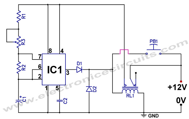
The standard 555 timer circuit consumes power from the battery even when the start push-button (PB1) is not pressed, due to a potential divider created by three 5kΩ resistors within the integrated circuit (IC). This power consumption, referred to...
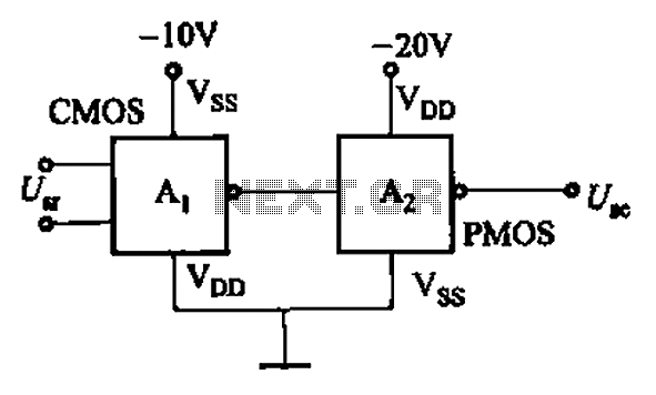
CMOS and PMOS cross interface circuit with PMOS integrated circuit providing high input impedance, allowing the input current to be negligible. The CMOS and PMOS interface circuit is illustrated in the accompanying figure. The CMOS and PMOS cross interface circuit...
This circuit utilizes the widely available LM3914 integrated circuit (IC). The IC is straightforward to operate, does not require external voltage regulators due to its built-in voltage regulation feature, and can be powered from nearly any voltage source. The LM3914...
A CD4017 is configured as a senary counter, with an input clock frequency of 300 Hz. Diodes VD1 to VD9 and resistors R1 to R3 form three three-input OR gates, which can each receive two 50 Hz three-phase wave...
This infrared alarm barrier is designed to detect individuals passing through doorways, corridors, and small gates. The transmitter emits an invisible beam of infrared light. When this beam is interrupted by a person, a buzzer connected to the receiver...
This receiver is designed around the widely used ZN414 integrated circuit (IC) and operates within the AM band, covering frequencies from 550 to 1600 KHz. To utilize the receiver for Longwave frequencies, it is necessary to replace the coil...