
Rear Fog Lamp For Vintage Cars

Fog lamps are essential safety features that enhance visibility during adverse weather conditions, such as fog, rain, or snow. The integration of a rear fog lamp in vintage cars not only complies with legal requirements but also improves the vehicle's safety profile.
The typical circuit for a rear fog lamp consists of a power source, a switch, and the fog lamp itself. The power source is usually the vehicle's battery, providing the necessary voltage to operate the lamp. A dedicated switch is often installed on the dashboard, allowing the driver to activate the fog lamp as needed.
In modern vehicles, the circuit may include additional components such as a relay, which helps manage the higher current that the fog lamp may draw, protecting the vehicle's wiring from overheating. The relay is typically activated by the switch, allowing a low-current signal to control a higher-current circuit.
Furthermore, the rear fog lamp is designed to emit a bright red light, which can be seen from a considerable distance, alerting drivers behind the vehicle of its presence. The lamp must be positioned at a specific height and angle according to regulatory standards to ensure optimal visibility without causing glare to other drivers.
In summary, the integration of a rear fog lamp in vintage cars not only fulfills legal obligations but also enhances safety through improved visibility in poor weather conditions. The circuit design for such lamps must consider various components to ensure reliability and compliance with safety standards.According to current legislation in many countries, vintage cars must also be fitted with a fog lamp at the rear. In modern cars, there is a bit of circui.. 🔗 External reference
Related Circuits
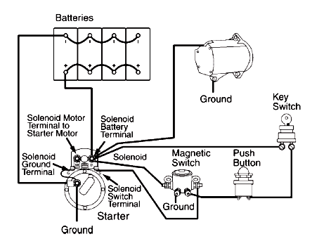
A circuit schematic for a basic heavy-duty electrical system that connects components such as the battery, starting motor, alternator, magnetic switch, ignition switch, and associated wiring. The heavy-duty electrical system circuit schematic is designed to provide reliable power management for...
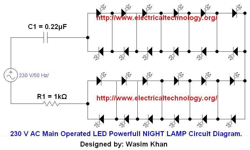
If you plan to use this circuit with a 110V 60Hz supply instead of a 230V 50Hz supply, or if you intend to modify this circuit, please refer to the section titled "Common Questions about this Circuit" found below...
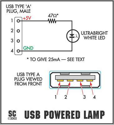
It connects to the USB port and is ideal for checking motherboard switch and jumper settings. Many users may recall a commercial product of a similar nature. This device serves as a USB-based diagnostic tool designed to facilitate the verification...
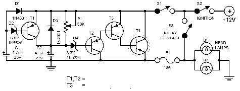
Every driver understands that intense light directed at the eyes can lead to hazardous consequences. Vehicles are equipped with a dimmer switch to reduce light intensity; however, some automotive headlamps remain excessively bright even when dimmed. The dimmer circuit...
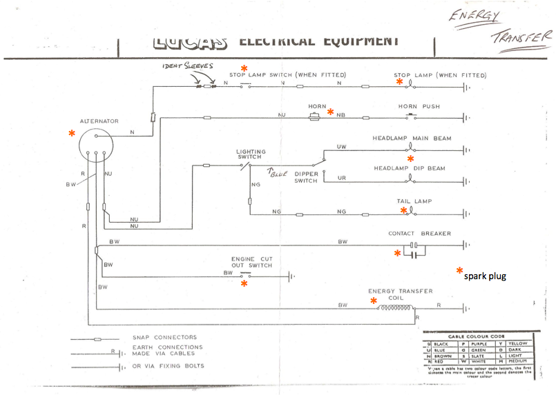
Timed precisely with the pistons' pumping, this component works with the ignition coil to create the voltage jump that causes the spark in the spark plug. The engine cut-out switch serves as an emergency button; when pressed, it provides...

This electronic lighting dimmer circuit is designed to control the brightness of incandescent lamps, but it is not suitable for fluorescent lamps. It operates with both 110V and 220V AC power sources. The circuit is connected in series with...