
Electronic Coin Toss

The electronic coin toss circuit utilizes the CD4049 integrated circuit, which serves as a hex inverting buffer and TTL driver. The primary function of this circuit is to simulate the randomness of a coin toss, providing a digital output that represents either heads or tails.
The CD4049 IC contains six independent inverters, which can be configured to create a simple random number generator. In this circuit, two outputs from the CD4049 can be used to represent the two possible outcomes of a coin toss. A resistor-capacitor (RC) timing network may be employed to introduce a delay, ensuring that the output stabilizes before being read as a result.
Power supply connections to the CD4049 are typically made using a standard voltage range of 3V to 15V, which is suitable for most TTL applications. The outputs can be connected to LEDs or a digital display to visually indicate the result of the coin toss.
To operate the circuit, a momentary switch can be incorporated to trigger the toss. When the switch is pressed, the circuit generates a random output based on the internal switching of the inverters, effectively simulating a coin flip. The simplicity of the design allows for easy implementation and modification, making it an excellent project for both beginners and experienced electronics enthusiasts.
The circuit can also be enhanced with additional features, such as sound output to indicate the result or a more complex random number generation algorithm, thereby increasing its functionality and user engagement.Electronic Coin Toss Circuit Diagram This is electronic coin toss circuit using one CD4049 IC (Hex inverting buffer and TTL driver). This IC.. 🔗 External reference
Related Circuits
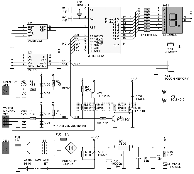
The following circuit illustrates the iButton Electronic Lock Schematic diagram. This circuit is based on the Atmel AT89C2051 integrated circuit (IC). Features include an onboard power supply comprising a transformer (T1) and a voltage regulator (U4), a bridge rectifier...
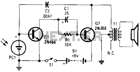
This electronic music maker utilizes an astable oscillator circuit that is regulated by a photocell. The intensity of light falling on the photocell influences the tone. By enclosing the circuit within a box, it is possible to manipulate the...

The objective of the circuit is to create an electronic dice using the functionality of a 555 timer integrated circuit operating in astable mode. The electronic dice circuit utilizes a 555 timer configured in astable mode to generate a series...
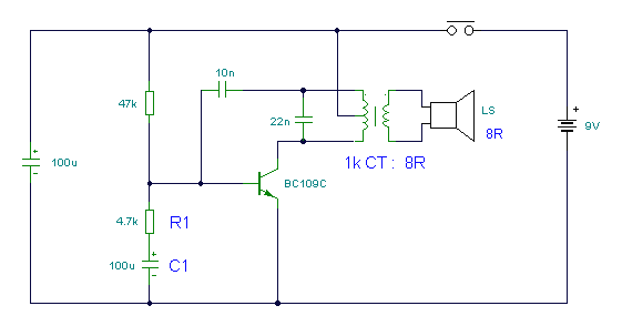
This circuit is a modified Hartley oscillator that incorporates additional components. It utilizes a small audio transformer, specifically the LT700 model. The primary winding is center-tapped with an impedance of 1 kΩ at 1 kHz, while the secondary winding...
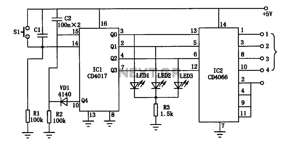
The electronic circuit diagram consists of the CD4017 and CD4066 components configured as a switch circuit. The CD4017 is a decade counter integrated circuit (IC) that can drive up to ten outputs, sequentially activating them based on clock pulses. It...
At times, it is quite frustrating to see street lights remaining switched on even during broad daylight. The current circuit for an automatic night light can effectively address this issue. This article explains how to construct such a system....