
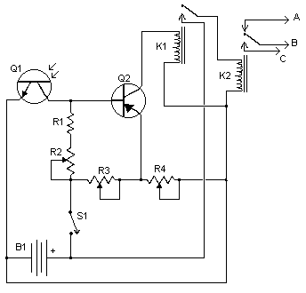
Reflected Infrared Light Switch

This circuit utilizes infrared (IR) light to detect the presence of a finger, allowing for a touchless activation mechanism. The core component of this circuit is an infrared LED that emits light, which is directed towards a phototransistor or photodiode positioned to receive the reflected IR light. When a finger comes into proximity of the IR LED, a portion of the emitted light reflects off the finger and is captured by the phototransistor.
The phototransistor is configured in such a way that the amount of light it receives directly influences its conductivity. As the reflected light intensity increases due to the presence of a finger, the phototransistor transitions from a non-conductive state to a conductive state. This change can be used to trigger a relay or a microcontroller input, effectively turning on or off a connected load.
To ensure reliable operation, the circuit may include additional components such as resistors to limit current through the IR LED and phototransistor, as well as capacitors for noise filtering. A potentiometer can also be included to adjust the sensitivity of the phototransistor, allowing for customization based on environmental lighting conditions.
This touchless switch circuit is particularly useful in applications where hygiene is a priority or where physical contact with a switch may be impractical. It can be implemented in various devices, including automatic doors, faucets, and lighting systems, enhancing user experience while maintaining functionality.Infrared light reflected off a finger is used to activate this switch circuit 🔗 External reference
Related Circuits
Operating high-beam headlights while driving on highways can significantly enhance visibility; however, it poses a blinding risk to other drivers. This straightforward circuit can be integrated into the headlight switch to facilitate automatic switching between high and low beam...
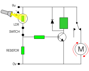
The following circuit illustrates a simple light sensor circuit diagram. Features include crocodile technology for simulating circuit operation, and an LDR (Light Dependent Resistor) is utilized. The simple light sensor circuit operates on the principle of light intensity detection using...
This circuit causes an LED to blink every half second. The duration of the blinking can be modified by changing the value of capacitor C1. Additionally, up to 18 more LEDs can be connected to this circuit, allowing for...

When the potentiometer is in the upper position, the capacitor charges rapidly through both 1k resistors and the diode, resulting in a brief positive interval and an extended negative interval, which dims the lamp to near darkness. Conversely, when...

A solar-powered garden light has been purchased, featuring a solar panel that charges batteries. When darkness falls, three LEDs illuminate until either light returns or the batteries deplete. The control box contains three Ni-MH AA batteries with a capacity...
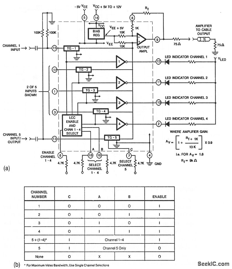
This circuit illustrates a CA3256 switch/amplifier configured for a direct-coupled output. One of four channels can be selected in parallel with channel 5. The analog switches of channels 1 to 4 are digitally controlled by logic. A VEE of...