
Regenerative AM Receivers

The regenerative (regen) receiver circuit is an oscillator design that operates by utilizing feedback to control the gain and maintain oscillation. This circuit typically incorporates a small-signal NPN transistor, such as the 2N4401, 2N3904, or 2N2222, which serves as the active amplification element. The gain control mechanism allows the user to adjust the feedback loop to a point just below the threshold of oscillation, enabling the generation of a weak oscillation that can be detected and amplified.
The core of the regen circuit consists of a tuning tank, which is formed by a combination of an inductor (often a tapped coil or multiple windings) and a variable tuning capacitor. This configuration allows for a wide tuning range since it eliminates the need for fixed capacitors, which can limit the circuit's versatility. The tuning capacitor is responsible for providing the total capacitance necessary for the tank circuit, and the tapped coil facilitates the introduction of feedback into the circuit.
Experimental values for the components can be utilized, as the specific values are not critical to the overall function of the circuit. This flexibility encourages experimentation and optimization based on available components. The output from the regen circuit is typically weak, necessitating the use of an external audio amplifier to drive headphones or speakers effectively. Suitable amplifiers can be referenced from dedicated audio amplifier resources.
While the regenerative design maximizes tuning range, it also requires the use of specially crafted coils, which can be a drawback for some users. The use of capacitive taps in the design enhances performance by allowing for precise control over the feedback loop, contributing to the stability and quality of the oscillation produced. Overall, the regenerative receiver circuit is a versatile and effective solution for radio frequency applications, particularly in low-power and experimental contexts.The regen is basically an oscillator circuit with a gain control that allows the user to adjust the feedback to a point just below oscillation or, quite often, just above the critical level such that a small oscillation is present. The typical regen uses a tapped coil or additional windings to connect into the tuning tank and the tuning capacitor provides the total tank capacitance.
The components are not critical and the values were pretty much the first ones found on the bench that were near the "right" value so don't hesitate to experiment. The transistor could be just about any small-signal NPN including the 2N4401, 2N3904, 2N2222, or others.
The audio output is fairly weak and will need an amplifier to drive headphones or a speaker. See the audio amplifier page for suitable amps. The advantage to this approach is that the tuning range is maximized since there are no fixed capacitors contributing to the tank. The disadvantage is that special, hand-made coils are required. The regens shown below use capacitive taps to achieve the re 🔗 External reference
Related Circuits
The usual procedure for producing sustained oscillations in tuned L-C networks involves overcoming circuit losses through designed-in positive feedback or regeneration. During the circuit's on-transient, oscillations build up, triggered by the thermal noise of circuit elements. Two possible situations...
This is a simple RF receiver mainly for low-distance digital radio receiver application. The analog output of this circuit should be connected to a schmitt-trigger signal conditioning circuit with a proper value capacitor (from collector of T3). L1 for...
The following is a translation of a section from the first book of the three-part series "Die Röhre im UKW Empfang" edited by Dr. Ing. Horst Rothe in 1952. This section describes a fully differential super-regenerative self-limiting FM detector....
Firstly because of the modulation process we generate at least two copies of the intelligence plus the carrier. For example consider a local radio station transmitting on say 900 Khz. This frequency will be very stable and held to...
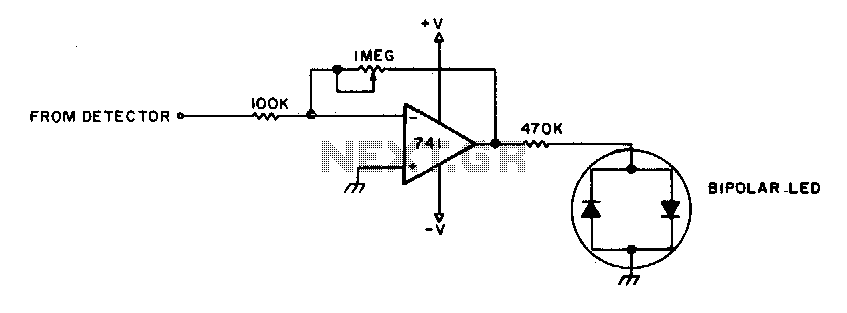
To adjust, tune into a station and adjust the I"M pot for a null. Then ask the station to modulate and fine-tune so modulation peaks do not light the LEDs. Stations are properly tuned when neither LED is lit. The...
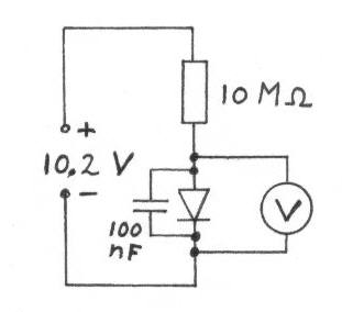
Diodes with a low voltage drop also exhibit a high reverse current (leakage current), which places a heavier load on the detector circuit, reducing the quality factor (Q) of the circuit and consequently lowering the voltage across the LC...