
regulated dc to dc converter

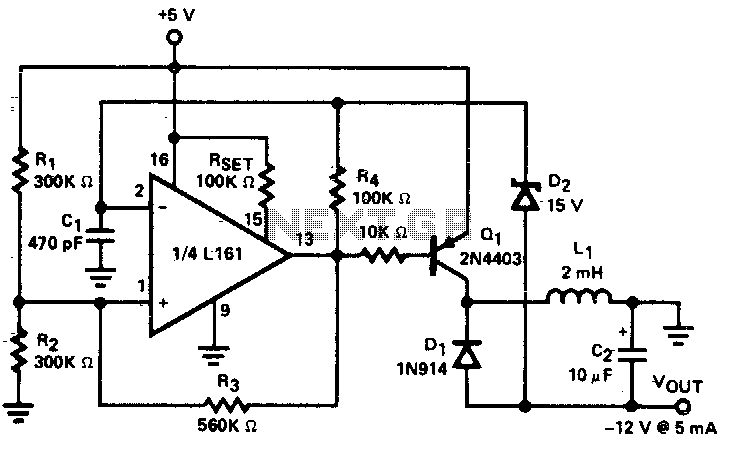
The circuit employs the L161 IC, which is known for its low power consumption characteristics, making it suitable for battery-operated devices and energy-efficient applications. The converter functions by utilizing a feedback mechanism to regulate the output voltage, ensuring that the desired 12V DC is consistently achieved from the 5V DC input.
Key components of the circuit include the L161 comparator, resistors for setting the feedback voltage, and capacitors for stabilizing the output and filtering any noise. The design may also incorporate inductors to smooth the transition between the input and output voltages, reducing ripple and improving overall performance.
The output current of 5mA indicates that this converter is intended for low-power applications, where efficiency and minimal energy loss are critical. The layout of the circuit should be carefully designed to minimize parasitic effects and ensure stable operation across varying load conditions.
In summary, this DC to DC converter circuit offers a compact and efficient solution for stepping up voltage levels in low-power applications, leveraging the capabilities of the L161 IC to provide reliable performance.Regulated DC to DC converter based on Micro Power Quad Comparator L161 IC that have ultra low power consumption, the circuit converts 5VDC to 12V DC at 5mA.. 🔗 External reference
Related Circuits
A DC/DC step-up converter is suitable for use in battery-powered equipment. This converter can be employed to generate supply voltages for internal circuits. The DC/DC step-up converter, also known as a boost converter, is a critical component in various electronic...
A low power DC to DC converter is created by integrating a flyback circuit with a square wave oscillator. The operating frequency is set at 20 kHz to reduce the size of the inductor (L1) and capacitor (C2). Regulation...
This circuit consists of a UJT oscillator in which the timing charge capacitor C2 is linearly dependent on the input signal voltage. The charging current is set by the voltage across resistor R5, which is accurately controlled by the...
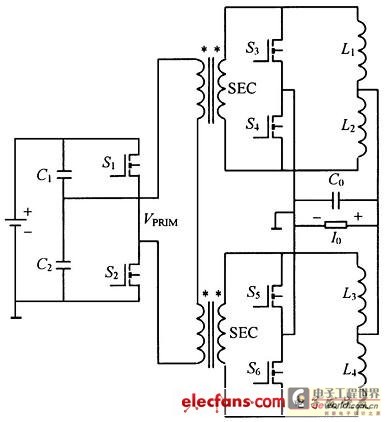
This structure significantly reduces electric current ripple on the filtering capacitance, thereby minimizing the inductive magnitude and overall size of the DC-DC converter. The converter operates at a switching frequency of 100 kHz with an input voltage of 48V....
This is a very sensitive 50Mc converter allowing you to receive the entire "Magic Band" (50Mc...52Mc) on your general coverage receiver (28Mc...30Mc). It receives all types of modulated transmissions. It all depends on the receiver used. I’ve tested this...
The timer is utilized in a conventional setup, with the exception that the timing resistor has been substituted with a current source derived from the operational amplifier DA1 (741). This modification enables the achievement of excellent linearity, exceeding 3%....