
Voltage to-frequency-converter

The described circuit is a Unijunction Transistor (UJT) oscillator, a type of relaxation oscillator known for its simplicity and effectiveness in generating pulse signals. The UJT operates based on the principle of negative resistance, allowing it to produce oscillations when connected to a charging capacitor and a resistor network.
In this configuration, capacitor C2 plays a crucial role as the timing element. Its charge time is directly influenced by the input signal voltage, which provides a variable timing characteristic. As the input voltage increases, the charging current flowing through resistor R5 also increases, leading to a faster charge time for C2. Conversely, a lower input voltage results in a slower charge time, creating a direct relationship between the input signal and the output frequency of the oscillator.
Resistor R5 is strategically placed in the circuit to regulate the charging current. The voltage across R5 is monitored and controlled by an amplifier, ensuring that the charging process remains stable and predictable. This feedback mechanism allows for precise control over the oscillation frequency and output signal characteristics, making the circuit suitable for various applications such as timers, pulse generators, and frequency modulation.
The UJT oscillator's output can be further refined by integrating additional components, such as filters or amplifiers, depending on the desired application. Overall, this circuit exemplifies a practical approach to generating oscillatory signals with adjustable frequency based on input conditions.This circuit consists of a UJT oscillator in which the timing charge capacitor C2 is linearly dependent on the input sigoal voltage. The charging current is set by the voltage across resistor R5. which is accurately controlled by the amplifier 🔗 External reference
Related Circuits
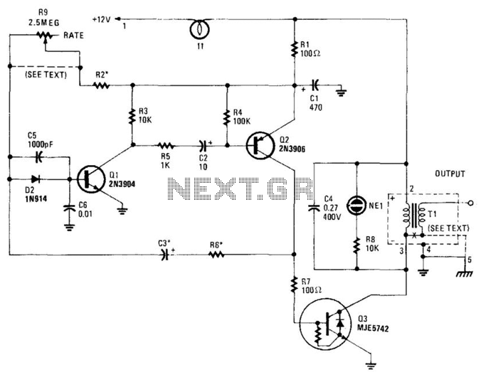
This high-voltage pulse supply generates pulses up to 30 kV. Q1 and Q2 form a multivibrator in conjunction with peripheral components R1 through R6, and C1, C2, C3, C5, C6, and D2. R9 adjusts the pulse repetition rate, while...
This simple circuit tests speakers, microphones, transformers, and voltage. It is essentially a very low-frequency oscillator that generates extremely short, distinctive pulses. The sound produced is easy to hear and allows for precise localization, making it ideal for checking...
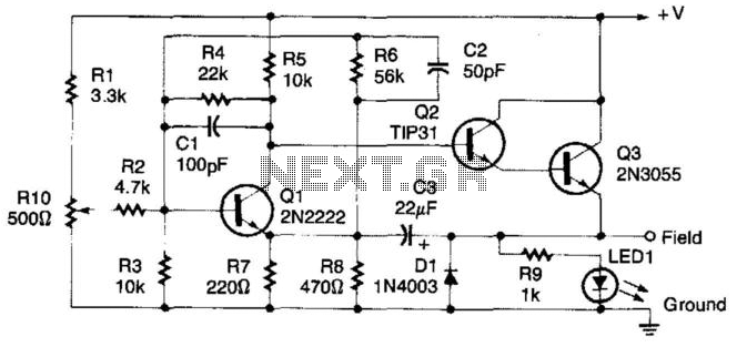
This regulator circuit can be used on an alternator that has one field terminal grounded. When the input voltage becomes too high, Q1 conducts, and the base of Q2 is driven toward ground, reducing the voltage fed to Q3....
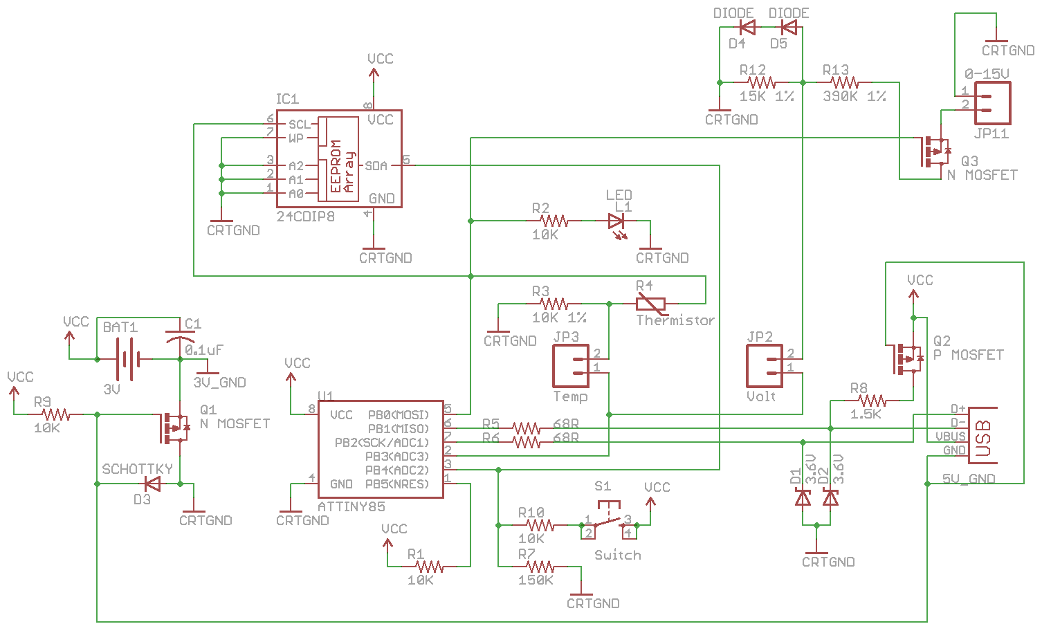
Combine the SATL and SAVL together. The schematic was updated with the voltage sensing circuit. A MOSFET was added to draw power from the voltage source only when needed. There are two jumpers, Temp and Volt, allowing the user...
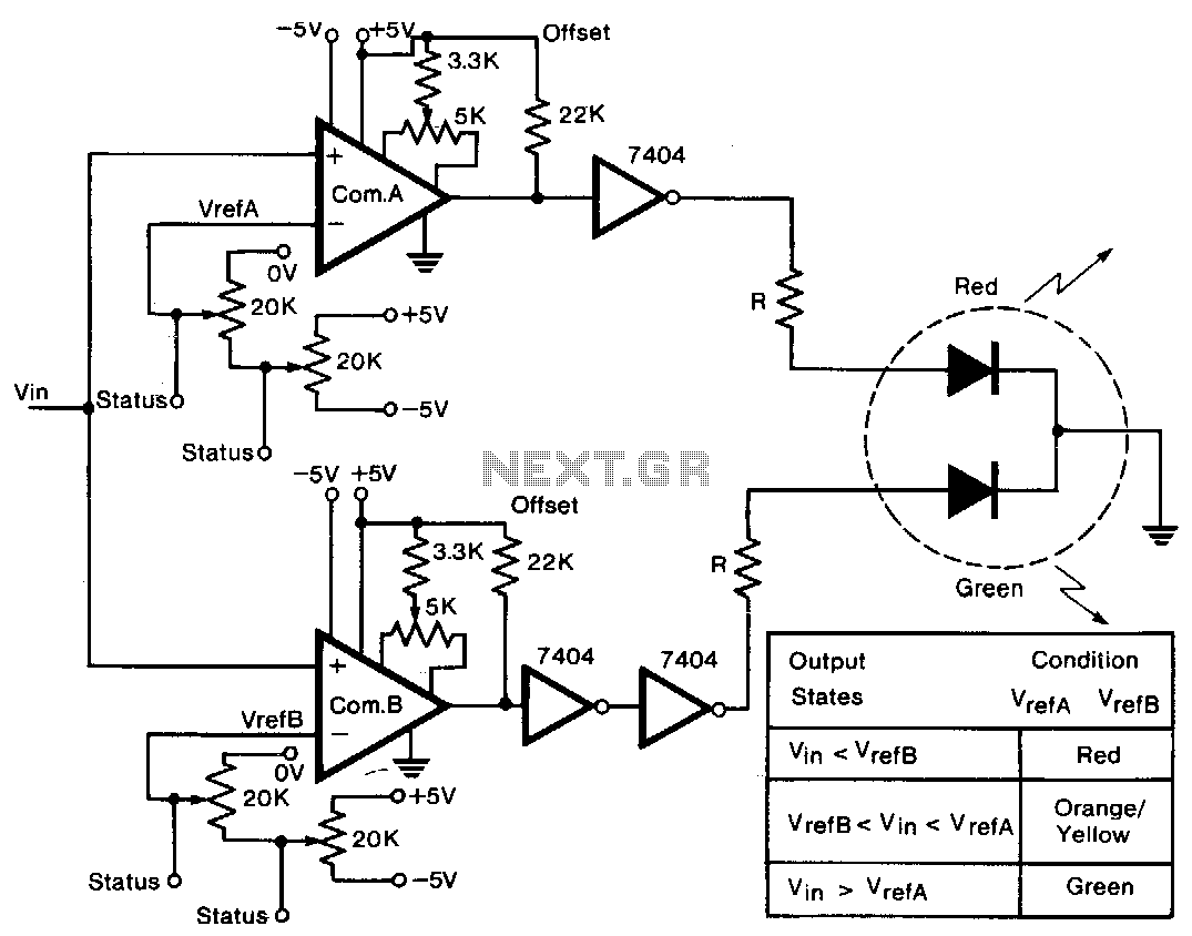
A tricolor LED serves as the visual indicator for voltage levels. The voltage to be measured is connected to two comparators in parallel. The first 20-KΩ trimmer sets a reference voltage between ±5 V, establishing the full-scale reference value....
This overvoltage protection or crowbar protection circuit is used where protection against high voltage surges is necessary. The circuit consists of several components. This overvoltage protection circuit, commonly referred to as a crowbar circuit, serves as a critical safety mechanism...