
regulator

The schematic described involves a transformer (T1) with four windings, crucial for the operation of the oscillator circuit. The configuration of the windings is essential for the magnetic coupling necessary for the oscillation of Q2. The feedback mechanism between T1-A and T1-B creates a self-oscillating circuit, where the increasing current in T1-B generates a magnetic field that induces voltage in T1-A, which in turn controls the state of Q2. The rapid switching of Q2 generates the necessary pulses for triggering the SCRs, which are critical for controlling the charging of the battery.
The operation of the SCRs is governed by the conditions of gate triggering and the voltage relationship between the anode and cathode. The design ensures that once the SCR conducts, it remains in the conducting state until the current falls to zero, which is a typical characteristic of SCRs. The inclusion of zener diode Z1 in the circuit serves a protective role, preventing overcharging by shutting down the oscillator when the battery reaches a certain voltage level.
This circuit design exemplifies an effective method of battery charging control utilizing traditional components, showcasing the principles of electromagnetic induction, feedback control, and semiconductor switching. The choice of transistors, such as the 2N2222A and 2N3053, indicates a focus on reliability and performance in the oscillator and switching roles, ensuring the circuit operates efficiently under varying load conditions.Malcolm Moore`s schematic is good, but it`s not enough for a dangerous man with a soldering iron to do anything useful with. Namely, what is T1 A coil(s) of some type, but the configuration Also Q1, Q2 values ditto SCRs. I was intending to respond to your query on Tuesday under the "`69 450 desmo regulator" thread so I`ll do both here.
If anyones eyes glaze over, go to the next message :-) Firstly regarding my schematic on Willy`s site: T1 is a transformer with four separate windings (coils), A B C & D. The dashed line is intended to indicate the windings are all on the same core. Where isolation is required, triggering SCRs via a trigger transformer was (is) a common industrial control technique in the days before optocouplers were readily available.
To understand how the circuit works it is best to start with Q2. If you imagine Q1 to be erased from the drawing, Q2 is a simple oscillator. The coil in it`s collector circuit (T1-B) is magnetically coupled to the coil in it`s base circuit (T1-A). When power is first applied Q2 will start to conduct. This causes an increasing current to start flowing in coil T1-B and so a changing magnetic field is produced in the transformer core.
The coil T1-A acts like a good little transformer secondary and a voltage is produced at it`s terminals. The coil is connected such that this voltage acts to turn Q2 off. The now reducing current in T1-B then produces a voltage in T1-A of opposite polarity to before and this turns Q2 on again.
The end result is Q2 rapidly turns on off on off etc. The other two coils on T1 are also secondaries and produce pulses of current that are applied to the gates of the SCRs. An SCR will start rectifying when it has BOTH the gate triggered AND the anode is +ve with respect to (wrt) the cathode.
For each SCR this condition occurs on every alternate opposite half cycle. To trigger the SCR, the gate must be +ve wrt the cathode. This can be repetitive pulses or a continuous current (see below). On each half cycle, once the SCR has started conducting, it will continue doing so until the anode-cathode current falls to zero again. Therefore the gate pulses after the start of conduction are redundant in that half cycle, but still continue.
The above has got current flowing into the battery. However when the battery is charged we need to prevent it overcharging by stopping the SCRs from turning on. If we stop the oscillator the trigger pulses will cease. This is easily achieved by clamping the base of Q2 to it`s emitter and that is what Q1 does (the emitter has the arrow head, the base is the line at right angles to the thick bar and the collector is the other terminal).
As the battery voltage rises zener Z1 will start to pass current, which will turn Q1 on. This clamps the base of Q2 to it`s emitter and so charging ceases. After the battery voltage later falls, Q1 stops conducting and the oscillator starts again. I can`t tell you the transistor type numbers in the one I dismantled because the metal cans of the transistors had lost their markings. There didn`t seem to be any imprint left on the epoxy that encased them either. However, the site previously posted here with the Moto Morini regulator led me to the Dutch Moto Morini club at: their technical page is which at the bottom of the page includes a hand drawn schematic of their later type for bridge rectifiers.
The control circuit is nearly identical to my drawing (although it is drawn as a mirror image). They quote Q1 as 2N2222A and Q2 as 2N3053. They also give information about the oscillator which indicates 🔗 External reference
Related Circuits
This is a low-dropout (LDO) regulator circuit, constructed using only a single PNP transistor. This circuit is directly related to load current. At very low... The low-dropout (LDO) regulator is a crucial component in power management systems, providing a stable...
A regulated and noise-free power supply voltage is essential for microcontrollers and other components such as amplifiers, filters, and GPS devices. Voltage surges in the supply voltage can permanently damage embedded systems. A voltage regulator must maintain the output...
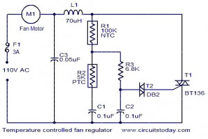
The function for automatically controlling the speed of a fan according to the temperature. Components: BT136 Triac, Capacitor, Resistor, Relay, Fan Motor. This circuit is designed to automatically adjust the speed of a fan based on the ambient temperature. It...
The design of solar panel systems with a lead-acid buffer battery typically allows for battery charging even during low sunlight conditions. However, this necessitates the use of a regulator to prevent overcharging during periods of abundant sunshine. Common solutions...
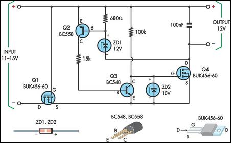
This circuit is designed to power a laptop computer using a solar power setup. The computer requires 12V at 3.3A. The circuit employs a linear regulator with a MOSFET (Q4) as the series pass device. A 100kΩ resistor provides...
As power supply switching frequencies increase, higher loop crossover frequencies are necessary to keep pace with the escalating load transient slew rate demands and to reduce the number and size of filter components. For voltage-mode-controlled supplies, the voltage loop...