
Relay driver with a 555

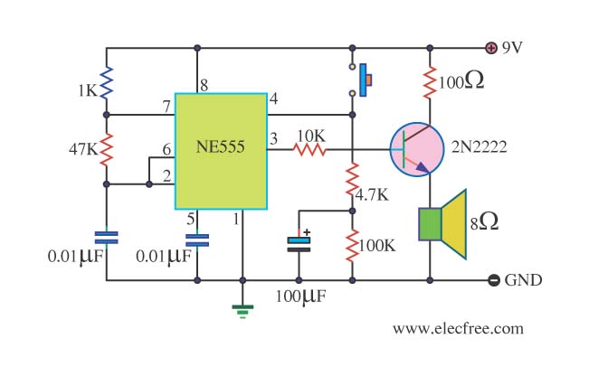
The described circuit utilizes a 555 timer in a bistable mode to control a relay based on a button press. The configuration allows for toggling the relay state when the button is activated. The threshold (pin 6) and trigger (pin 2) inputs are stabilized at half the supply voltage through two equal 10K resistors, ensuring a reliable switching action.
When the button is pressed, the capacitor connected to the circuit charges, momentarily raising the voltage at pins 2 and 6. This triggers the timer, causing the output at pin 3 to switch states. The output remains high until the button is released, at which point the capacitor discharges, allowing the circuit to return to its previous state based on the new voltage levels at the inputs.
The selection of components is flexible; however, it is critical that the resistors at pins 2 and 6 maintain equal values to ensure proper operation. It is recommended that the resistor connected to the capacitor be at least ten times greater than the other resistors to maintain the desired timing characteristics.
An advantage of this design is its large hysteresis range, which minimizes the risk of false triggering due to noise or fluctuations in the input signal. This feature is particularly beneficial in environments with electrical interference. The simplicity of the circuit, requiring only a few components, further enhances its practicality for various applications.
One drawback noted is the potential for the relay to engage upon initial power-up, which can be mitigated by incorporating a reset mechanism. By connecting pin 4 to a resistor-capacitor (RC) network, the reset pin can be held low temporarily during power-up, ensuring that the output is reset before normal operation begins.
In automotive applications, a 100-ohm resistor and a 100uF capacitor may be added to the power supply line to filter out noise, although these components are not strictly necessary for the circuit's operation. The design remains functional without them, but their inclusion can enhance reliability in noisy environments.This 555 timer circuit below toggles a relay when a button is pressed. Pins 2 and 6, the threshold and trigger inputs, are held at 1/2 the supply voltage by the two 10K resistors. When the output is high, the capacitor charges through the 100K resistor, and discharges when the output is low.
When the button is pressed, the capacitor voltage is applied to pins 2 and 6 which causes the output to change to the opposite state. When the button is released, the capacitor will charge or discharge to the new level at the output (pin 3).
The parts are not critical, the resistors can be somewhat higher or lower, but the 2 resistors at pins 2 and 6 should be equal values, and the resistor connected to the cap should be 10 times greater or more. Advantages of this circuit are the large hystersis range at the input which avoids false triggering, and only a few parts are needed for construction.
One disadvantage is the relay may be engaged when power is first applied. To solve this problem, you could tie the reset line (pin 4) to another resistor/capacitor combination with the capacitor at ground and the resistor at the +V point. This will cause pin 4 to be held near ground for a short period which will reset the output when power is applied.
The 100 ohm resistor and 100uF capacitor serve to filter noise on the supply line if the circuit is used in a automotive application. They may not be necessary. The circuit may work well without those parts. 🔗 External reference
Related Circuits
This calculator computes the resistor and capacitor values for a NE555 timer chip configured as an astable multivibrator (oscillator) or square wave generator. By entering the desired duty cycle and frequency, the calculator provides suitable values for the resistors...
This is a danger beep circuit. It uses a 555 integrated circuit configured as a stable multivibrator that provides a duty cycle of 5% to drive a loudspeaker. The danger beep circuit utilizes the 555 timer IC, a versatile and...
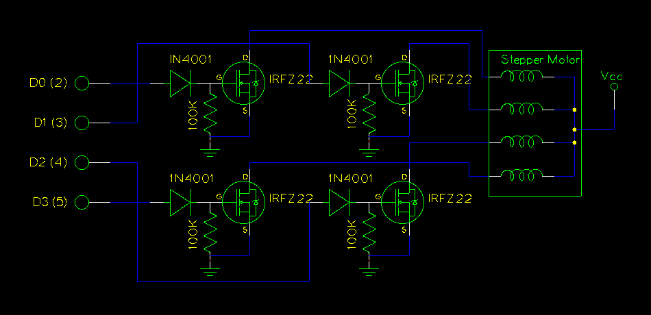
The use of a PC's parallel port provides a convenient method for controlling a stepper motor. For unipolar stepper motors, it is possible to control up to two motors using the 8-bit data line. Typically, a Darlington driver, such...
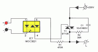
The primary advantage of a solid-state relay (SSR) over a traditional electromagnetic relay (EMR) is its reduced wear and tear, which enhances its longevity. The S201S01 model from Clear-Cut serves as an exemplary representation of this technology. The following...
Circuit to close a relay when any phone extension is off-hook. Voltage at the gate of the MOSFET should be negative (1-3 volts) with respect to the source when phones are on-hook. Voltage at the gate should be positive...
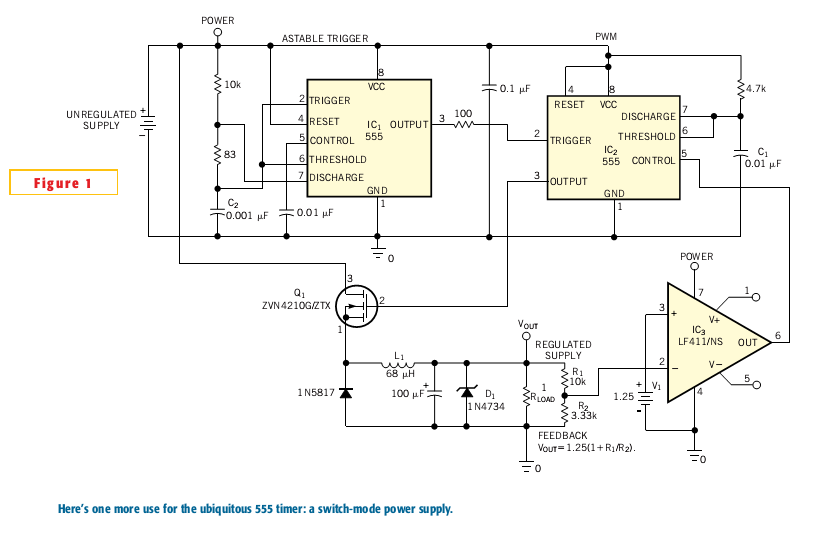
Most switch-mode power supplies utilize a PWM (pulse-width-modulated) output that is regulated through voltage feedback. A 555-timer IC can be used to generate PWM at a low cost. The circuit diagram illustrates how to convert a 555 PWM circuit...