
relay flasher circuit

The circuit employs the 555 Timer IC, which is widely recognized for its versatility in timing applications. In this astable configuration, the 555 Timer continuously switches between its high and low states, generating a square wave output at pin 3. The frequency of this output is determined by the resistors and capacitors connected to the timer. The 100K variable resistor allows for fine-tuning of the timing interval, thus adjusting the flashing rate of the relay.
The relay serves as an electromechanical switch that can control higher voltage loads. When the output at pin 3 goes high, it energizes the relay coil, closing the contacts and allowing current to flow to the connected load. Conversely, when the output goes low, the relay coil is de-energized, opening the contacts and interrupting the current flow to the load. This on/off cycling creates the desired flashing effect.
Powering the circuit at 6, 9, or 12V DC offers flexibility, but it is crucial to match the relay's voltage rating to the supply voltage to prevent damage. This configuration allows for a variety of applications, such as controlling lights, motors, or other devices that require intermittent operation. The design is straightforward, making it suitable for both beginners and experienced electronics enthusiasts looking to implement a reliable timing solution in their projects.In this circuit the 555 Timer IC is connected as a astable multivibator and a 12 volt relay is derived through the pin 3 of the IC. The IC generates continues pulses at pin 3 which will activate and deactivate or flash the relay accordingly.
The flashing rate per second can be controlled by the 100K variable resistor. The circuit can be operated w ith 6, 9 or 12V DC but make sure to use the same voltage relay when operating with 6 or 9 volts. . In the place of load you can connect any appliance which you want to ON and OFF. 🔗 External reference
Related Circuits

The circuit in Figure 1 is a 4-bit asynchronous counter, also known as a ripple counter. It consists of four J-K flip-flops with their J and K inputs connected to logic 1. This configuration causes the output of each...
Which switch mode power supply (SMPS) topology should one start with? Although the schematic of a full-bridge looks a bit complicated compared to push-pull and half-bridge designs, sticking straight to a full-bridge topology or its smaller version, the half-bridge,...
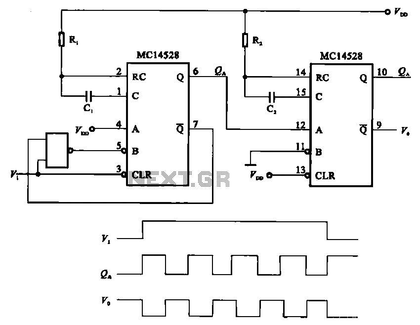
The pulse generating circuit monitors signals using monostable flip-flops. It generates a single-shot output signal based on the input pulse signal. A key signal from the monostable flip-flops is represented in a formula, with the input (V1) and output...
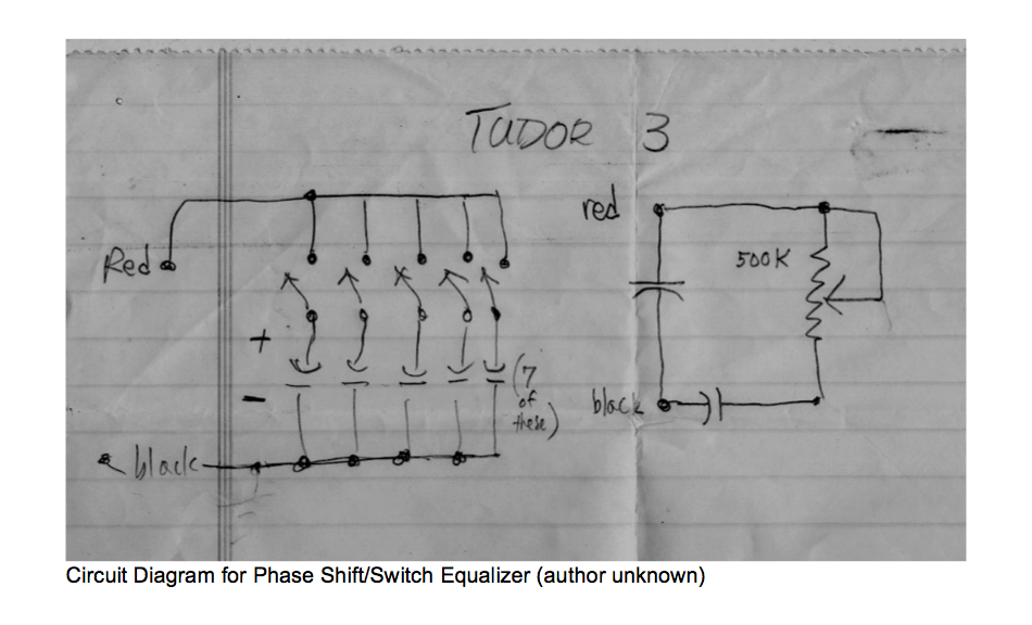
This circuit allows for the adjustment of resistance using a potentiometer and the adjustment of capacitance by opening or closing switches. By manipulating the configuration of these switches, various combinations can be achieved to obtain different effective capacitance values....

Figure 283 illustrates a blackout emergency lighting controller designed for straightforward external installation with two leads. This controller can directly replace the P Chan Tong Ge opening. Under normal power conditions, it functions like a conventional switch to control...

The circuit diagram illustrates a digital precision pressure tester using the MAX1457 integrated circuit with an external ROM selection of the 93C66 type, which is a 4096-bit E2PROM. Upon powering on, the MCS pin is pulled to a high...