
Two Flashing LEDs Circuit

The circuit operates by utilizing two LEDs that flash alternately at varying speeds, which can be adjusted according to user preference. The core components include two potentiometers, which serve as variable resistors to modify the timing intervals for the flashing LEDs. The active components typically include a timer IC, such as the 555 timer, configured in astable mode to generate a square wave output. This output is then used to drive the LEDs.
Passive components such as resistors and capacitors are also integrated into the circuit to set the frequency of the flashing and to ensure the LEDs operate within their specified current limits. The resistors limit the current flowing through the LEDs, while the capacitors help to stabilize the timing circuit and determine the flashing rate alongside the potentiometers.
For assembly, the components can be laid out on a veroboard or a general-purpose PCB, allowing for flexibility in design. Proper attention should be given to the orientation of the LEDs, as they are polarized components. The schematic diagram typically includes the connections between the timer IC, the LEDs, the potentiometers, and the power supply, ensuring clarity in the assembly process.
This circuit not only serves as an excellent introduction to basic electronics for beginners but also provides practical experience in soldering and layout design. Its versatility allows for adaptation in various projects, making it a valuable addition to any electronics toolkit.Here is the circuit diagram of Two Flashing LED`s for different applications (such as model construction), and recreational. Having adjustable flashing speed with two potentiometers. It is the collection of a few active and passive components. This circuit is very easy to built ( a good idea for beginners ) and can be build on a general purpose pcb or on a veroboard.
The complete picture and schematic of this project is shown below.. 🔗 External reference
Related Circuits
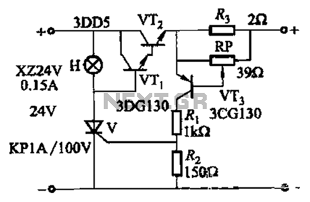
By adjusting Ro or RP, the current setpoint can be modified. The circuit illustrated in Figure 14-98 features overcurrent protection using a thyristor and transistors VTi and VT2, which immediately cut off the power when an overcurrent condition is...
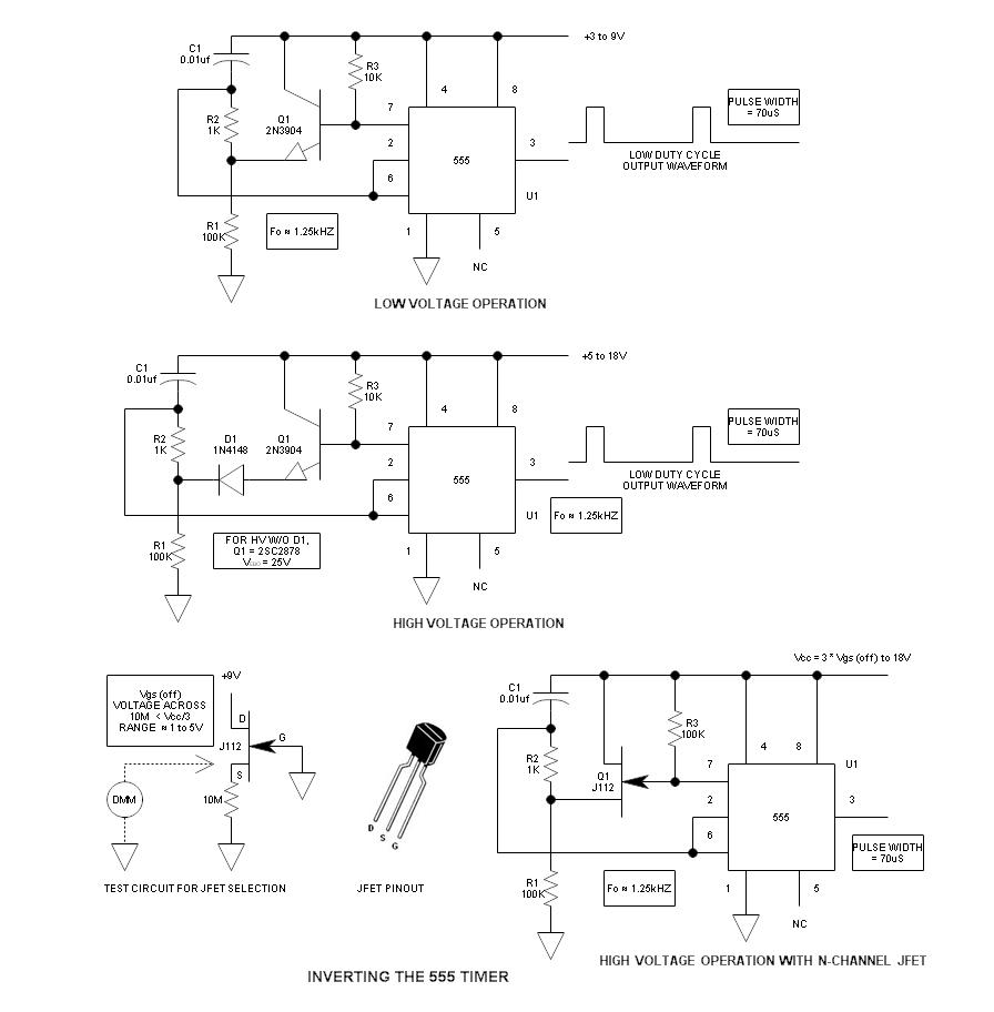
When using the 555 timer, the output polarity often appears to be incorrect, as the 555 typically cannot produce a duty cycle of less than 50%. This inverted 555 circuit is capable of generating duty cycles below 50%. The...
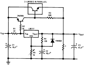
The following circuit diagram illustrates the application of the LM117 as a high current adjustable regulator. The LM117 is capable of supplying more than 1.5A. The LM117 is a popular adjustable voltage regulator that is designed to provide a stable...
This circuit utilizes an MC3392 low-side protected switch in conjunction with an MC1455 timing circuit to create a dimmer control for automotive instrumentation panel lamps. The brightness of incandescent lamps is adjustable through Pulse Width Modulation (PWM) applied to...
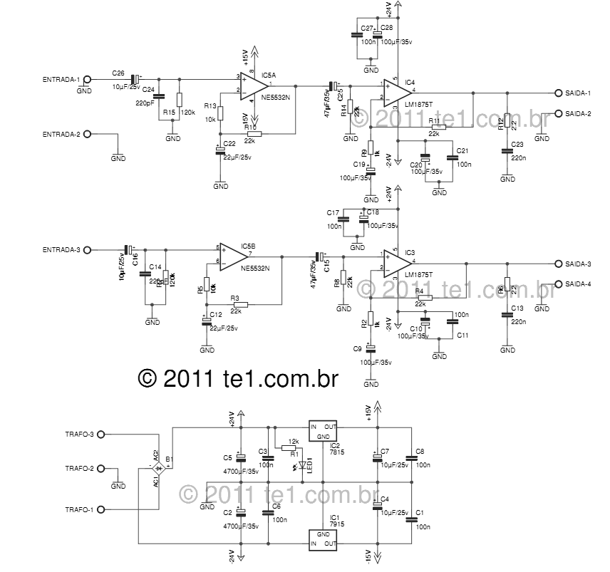
The LM1875 delivers 20 watts into a 4 or 8-ohm load on ±25V supplies. Using an 8-ohm load and ±30V supplies, over 30 watts of power may be delivered. The amplifier is designed to operate with a minimum of...
This circuit is housed in a compact enclosure and is positioned within the refrigerator, either near the lamp or at the door opening. When the refrigerator door is closed, the interior remains dark, causing the photoresistor R2 to exhibit...