
RF Decibel Meter Circuit

A DIY RF decibel meter serves as a valuable tool for measuring the power levels of radio frequency (RF) signals. This instrument is particularly useful in radio workshops for both amateur and professional applications. The primary function of the device is to provide accurate readings of RF power, typically expressed in decibels (dB), which is a logarithmic unit used to describe ratios of power levels.
The design of a DIY RF power meter typically involves several key components, including a directional coupler, a diode detector, an analog or digital voltmeter, and a microcontroller for signal processing. The directional coupler is responsible for sampling the RF signal without significantly affecting the transmission line. It allows a portion of the RF signal to be fed into the detector while passing the majority of the signal through to the load.
The diode detector converts the RF voltage to a corresponding DC voltage, which is proportional to the power of the RF signal. This DC voltage is then measured by the voltmeter or processed by a microcontroller, which can provide a digital readout of the power level in decibels. Calibration of the meter is essential to ensure accurate readings, and this can be achieved by comparing the meter's output to known reference levels.
The overall construction of the DIY RF power meter may involve a printed circuit board (PCB) to house the components, along with adequate shielding to minimize interference from external RF sources. Additionally, incorporating features such as a display for real-time readings and the ability to log measurements can enhance the utility of the device.
In conclusion, a DIY RF decibel meter is an invaluable asset for anyone working with radio frequencies, allowing for precise power level measurements without the need for expensive commercial equipment.An DIY RF decibel (or power) meter is an indispensable instrument in any radio workshop. Unfortunately, accurate, wideband models are fairly expensive, and.. 🔗 External reference
Related Circuits
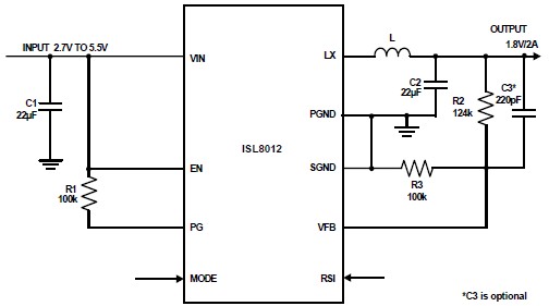
The ISL8012 is a high-efficiency, monolithic, synchronous step-down DC-DC converter that can be designed into a simple electronic project. It supports a maximum continuous output current of up to 2A from an input supply range of 2.7V to 5.5V....
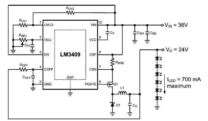
This dimming-controlled LED driver electronic circuit requires an input voltage of 36 volts and will provide an output voltage of 24 volts at a maximum current of 700 mA. The described dimming-controlled LED driver circuit is designed to efficiently convert...

This small device can be aimed at a television to jam the remote control signal. The circuit design is straightforward. A 555 timer is configured as an astable multivibrator operating at a frequency of approximately 38 kHz, which is...
T1 and T2 in the circuit form the inherent oscillator, while T3 serves as the output stage. The network consists of a high-pass filter (C3, C4, R6, and R7) and a low-pass filter. The output from this network is...
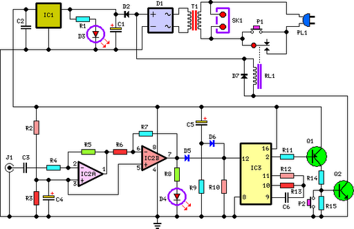
This circuit deactivates an amplifier or any connected device when a low-level audio signal at its input is absent for at least 15 minutes. Pressing P1 turns the device on, supplying power to any appliance connected to SK1. The...
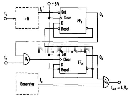
This circuit generates an output frequency that is linearly proportional to the ratio of two input frequencies. Each pulse of the bias frequency will open a switch for a period equal to half of the second input frequency, allowing...