
rem bell circuit

The remote telephone bell ringer circuit is designed to enhance the auditory signaling capability of standard telephones. The circuit operates by detecting the ringing signal from the telephone line, which is typically a low-voltage AC signal. Upon detection, the circuit activates a TRIAC or SCR (Q1 or Q2) to control the power delivered to an external bell.
The use of a TRIAC or SCR allows for efficient switching of higher voltage and current levels required by large bells. The choice of these components must consider their voltage ratings and current capacities to ensure reliable operation. Q2, which directly controls the bell, must be rated to handle the maximum current that the bell will draw during operation.
The circuit includes an opto-isolator, which serves a dual purpose. First, it provides electrical isolation between the telephone line and the power supply, protecting sensitive components from voltage spikes or transients that may occur on the phone line. Second, it minimizes the risk of ground loops, which can introduce noise and interference into the circuit, potentially affecting performance.
Adjustments to accommodate various supply voltages can be made by modifying resistor values or using different power supply configurations, ensuring the circuit remains versatile for different applications. It is also crucial to adhere to local regulations concerning the connection of homemade devices to telephone lines, as non-compliance can result in penalties or safety hazards.
Overall, this remote telephone bell ringer circuit offers a practical solution for enhancing the ringing capabilities of telephones in environments where traditional ringers are insufficient.This remote telephone bell ringer allows you to use a large (and loud) external bell in place or in addition to the built in (and rather wussy) ringer in most modern telephones. This is ideal for large outdoor areas, noisy shops or those hard of hearing. Most any large bell can be used as the circuit can be easily adjusted for various supply volta ges. Virtually any TRIAC and SCR will work for Q1 and Q2 as long as the voltage rating is high enough. Q2 needs enough current capacity to handle the full load of the bell. Make sure to check with local authorities before you connect a homemade device to your phone lines. Some areas mandate that only approved devices can be connected to the loop. This circuit provides an opto-isolator to prevent cosstalk between the phone line and power supply as well as to avoid ground loops. 🔗 External reference
Related Circuits
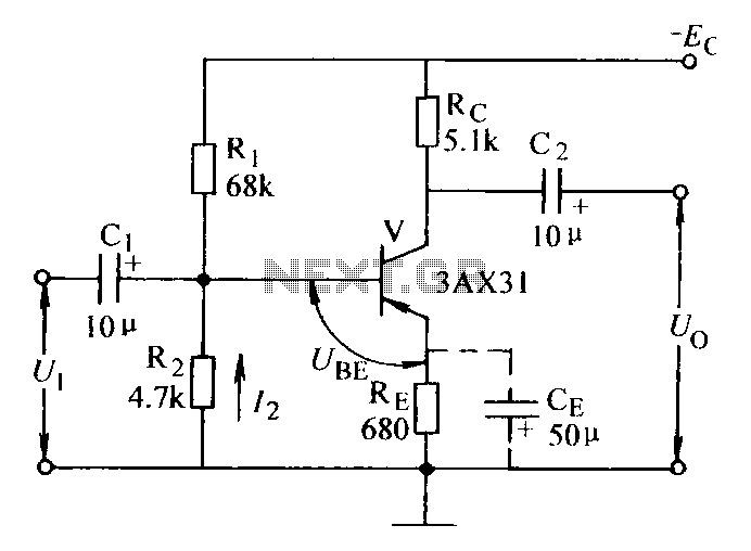
Current negative feedback voltage divider biased circuit diagram. The current negative feedback voltage divider biased circuit is a configuration commonly used in electronic amplifiers to stabilize the operating point and improve linearity. This circuit typically consists of an amplifier, a...
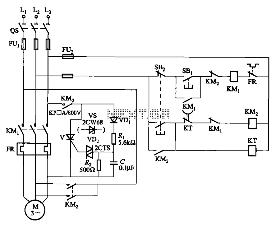
The circuit illustrated in Figure 3-148 eliminates the requirement for a step-down transformer by utilizing a thyristor for brake control in small capacity asynchronous motor braking applications. Upon shutdown, the contactor KM1 releases, while contactor KM2 engages the brake...
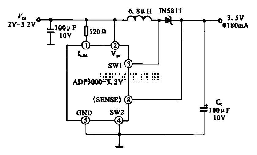
Boost 3.5V regulator circuit. This chip can boost or create a stable voltage supply from approximately 3V DC to a DC voltage of 3.5V. The boost regulator circuit is designed to increase a lower DC voltage, specifically from around 3V...
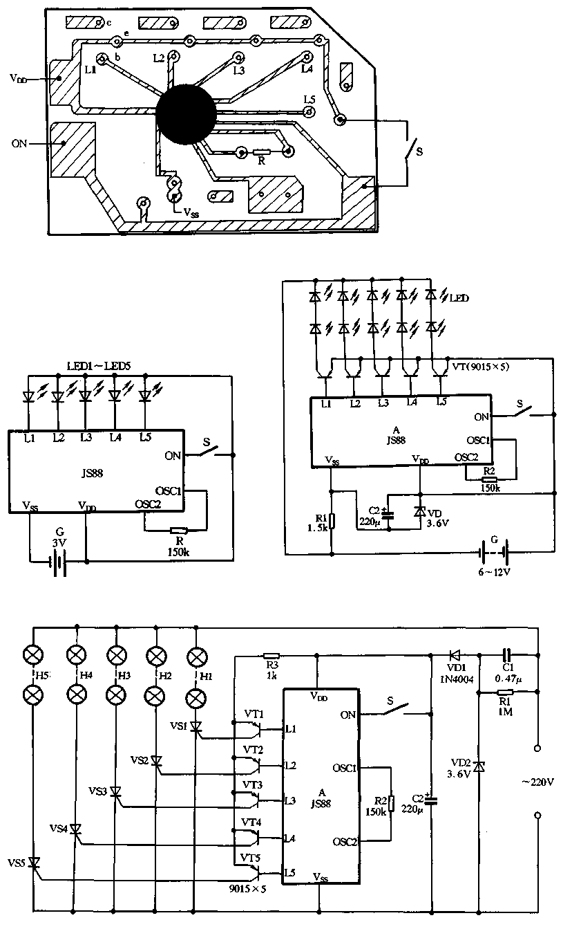
Figure 2-39 illustrates a typical application circuit for the JS88 manifold, which includes an oscillation resistor (R) that allows for fine-tuning of the water flicker frequency. When switch (S) is closed, components L1 to L5 sequentially output low signals...

FIG IC, ICR, Ri, R, and AN composition form a bistable contact circuit with a Ge transistor. It includes components such as ICc, lc, c2, and Dj, and is associated with a one-shot delay circuit. The circuit can be...
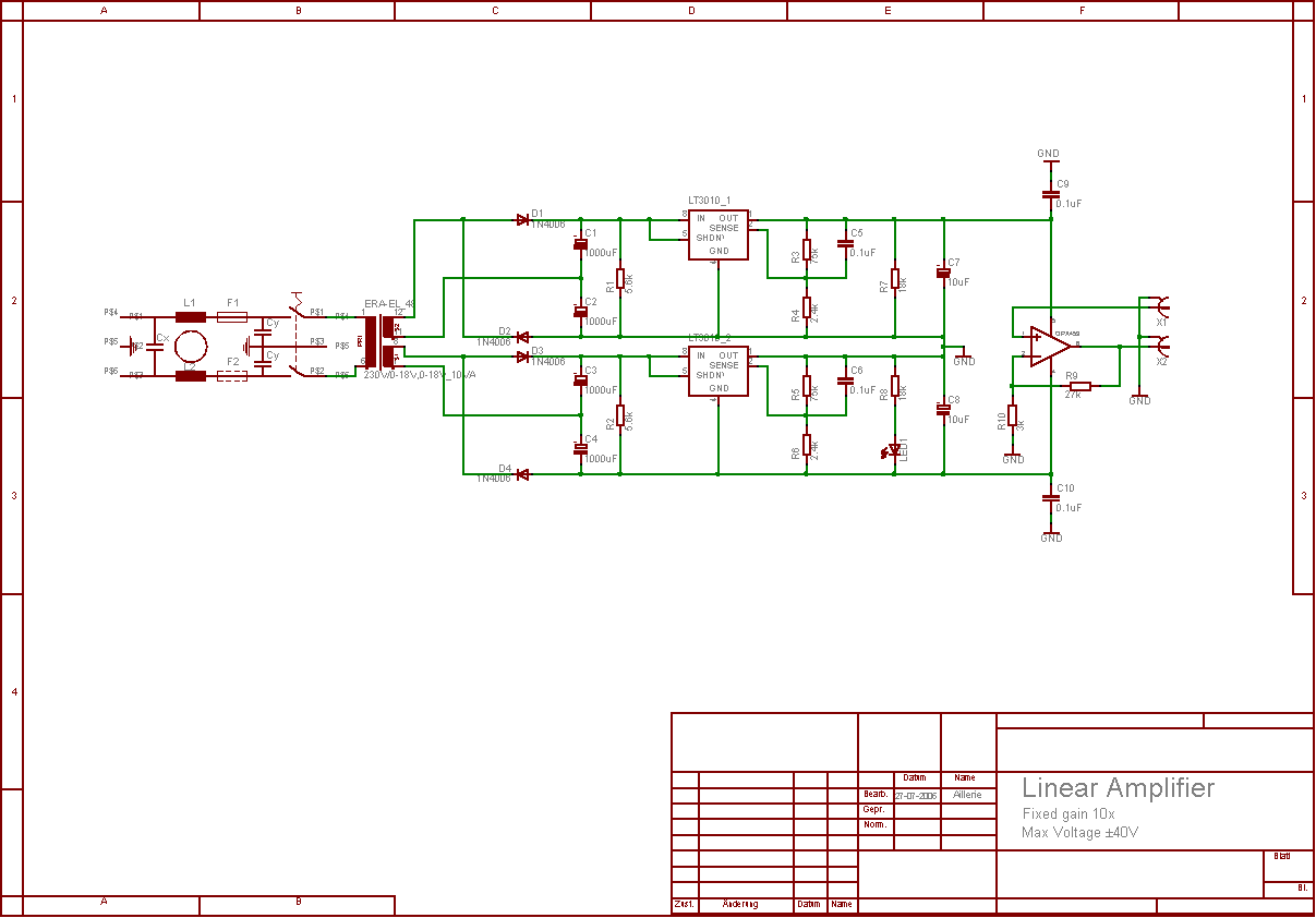
The aim of this project was to develop a linear analogue amplifier designed for laboratory use. This amplifier has to realise a voltage amplification of 10x and is intended to amplify function generator signals for tests. Power supply requirements:...