
Infrared Remote Control On/Off Switch Electrical Mini Project

The Infrared Remote Control On/Off Switch project utilizes an 8-bit microcontroller, specifically the AT89C2051, which serves as the central processing unit for the system. The microcontroller is programmed to interpret signals received from the infrared remote control, enabling it to execute commands for switching various electrical devices on or off.
The system architecture comprises several key components: the infrared receiver module, the microcontroller, the relay driver circuit, and the relays themselves. The infrared receiver module captures the signals emitted by the remote control. These signals are then decoded by the microcontroller, which processes the command and activates the appropriate relay to control the connected appliance.
The block diagram provides a visual representation of the system's functional flow, illustrating how the input signals from the remote control are processed to produce the desired output. The circuit diagram details the connections and components used, including the power supply, microcontroller pin configuration, and relay connections.
The project also includes the source code for the AT89C2051 microcontroller, which is essential for programming the device to respond accurately to the remote control inputs. The code typically includes initialization routines, signal decoding algorithms, and relay control functions, ensuring seamless operation of the system.
This project not only demonstrates the practical application of infrared technology in home automation but also serves as an educational tool for understanding microcontroller programming, circuit design, and the integration of various electronic components.This is a good Electrical project report on Infrared Remote Control On/Off Switch and was Submitted in partial fulfillment of the requirements for the award of the degree of Bachelor of Engineering in Electrical Engineering and is used to switch on/off the Home Appliances by using a standard Remote control. The system is used to switch on/off upto six electrical devices. You can also Subscribe to FINAL YEAR PROJECT`S by Email for more such Projects and Seminar. This system uses 8 bit Microcontroller AT89C2051 and report also has block diagram and circuit diagram of Infrared Remote Control On/Off. An infra-red remote control is a component of an electronics device, most commonly a television set, used for operating the device wirelessly from a short line-of-sight distance.
Source code of microcontroller. Use this report for your reference and study only. 🔗 External reference
Related Circuits
Chris from PyroElectro.com has an informative article detailing a do-it-yourself radar system constructed using the PIC18F452 microcontroller. This project is an excellent hobbyist endeavor, although the schematic design is quite complex. The system integrates three primary components to form...
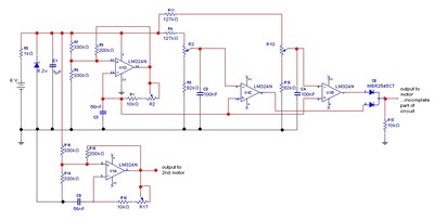
The goal is to control the speed of a 6-volt brush DC motor using a linear potentiometer and to create an oscillating speed effect, with the oscillation frequency also adjustable via a linear potentiometer. The desired complete cycle peak-to-peak...
This bulletin outlines the applications, design features, equipment arrangement, and space planning for the type 230 controllers. These controllers are designed for the control and protection of induction motors or transformers in 2300-4160 volt systems. Each type 230 controller...
What is the recommended frequency for the Low Pass Filter used to control the contrast of an LCD? I want to adjust the contrast of an LCD using PWM. To effectively control the contrast of an LCD using Pulse Width...

This circuit comprises a 15V TOP224Y, 2A output DC switching power supply. It utilizes three integrated circuits: IC1 is a monolithic regulator (TOP224Y), IC2 is an optocoupler (NEC2501), and IC3 is a precision voltage reference (TL431). The TL431 (IC3)...

After restoring its engine and other mechanical components to optimal condition, the next step involved adding aesthetic lighting. A visit to a local electronics store resulted in the discovery of 12V DC-operated LED strips, which were ideal for the...