
2Y-Y-2 - connection four-speed motor contactor control circuit

This circuit design is aimed at providing efficient control over a small motor while ensuring safety and operational flexibility. The use of an intermediate relay instead of a contactor simplifies the circuit when dealing with lower power requirements, reducing both cost and complexity.
The four-speed forward and one-speed reverse operation is achieved through a series of push buttons (SB1 to SB10) that are wired to control the motor's speed settings. Each button corresponds to a specific speed, allowing for quick adjustments based on operational needs. The interlocking feature is critical; it prevents two speeds from being activated simultaneously, which could lead to system malfunctions or damage. This is accomplished by using normally closed contacts that open when one speed is selected, thereby disabling the others.
The design also emphasizes user convenience, as it allows for immediate motor speed selection without prior stopping. This feature is particularly useful in applications requiring rapid adjustments. The ability to maintain operational speed while engaging the start buttons enhances the circuit's functionality, making it suitable for various applications where quick response times are essential.
In summary, the circuit provides a reliable and efficient method for controlling a small motor with multiple speed settings while ensuring safety through interlocking mechanisms. Circuit shown in Figure 3-120. If the motor capacity is small (less than the rated current 5A), it can use an intermediate relay (contact a few more) instead of the contactor. The line can be achieved in four speed forward running and reverse running one of the most high-speed e matter and cause a short circuit through the circuit for interlocking contactor normally closed auxiliary contact, to ensure that the two speeds can not start it. The line allows any start button is pressed, the corresponding speed can be obtained immediately without having to press the stop button in advance, regardless of motor speed also at work.
Figure, SBl and SB6, SB2 and SB7, SB3 and SBs, SB4 and SBa, SBs are linked with SBao button.
Related Circuits
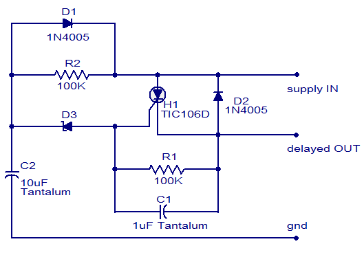
The circuit diagram presented is of a straightforward DC power delay circuit utilizing a silicon-controlled rectifier (SCR). This circuit is quite useful and can be applied in various scenarios. The operation of this circuit is uncomplicated. Upon the application...
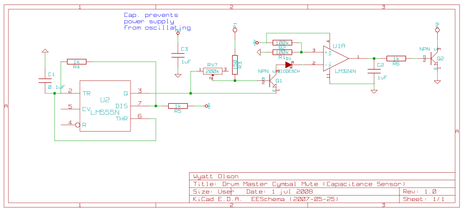
This page contains various small circuits created over time. Some circuits are trivial, while others are more complex, but all are intended to be useful for a variety of projects. Most include both the schematics and the source (KiCad)...

Some good inverter circuits I found oscillate at approximately 50 to 60 Hz. They are likely capable of handling up to two amps; any more than that will cause them to automatically shut off. If there are questions, please...
The pyroelectric infrared sensor head operates as illustrated in the accompanying figure. Upon detecting an infrared signal from a human body within its monitoring zone, the sensor head generates a positive pulse signal. This signal is transmitted to the...
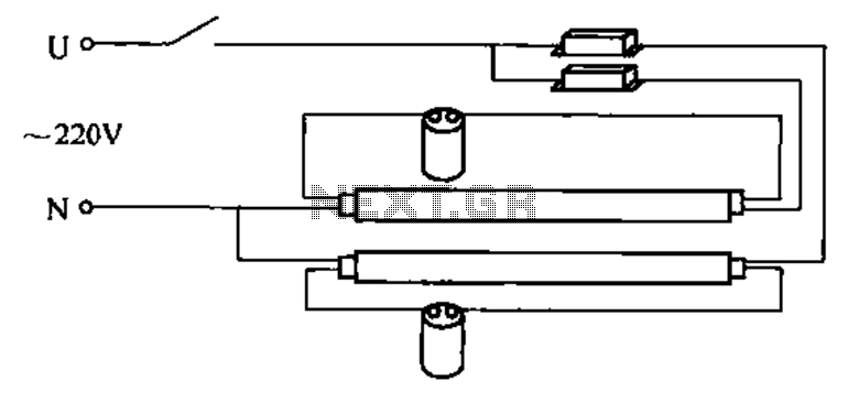
A double tube fluorescent lighting circuit is illustrated. In certain situations, a single tube light may not fulfill the lighting requirements, necessitating the use of double tube lighting. The physical installation is depicted in the circuit of a double...
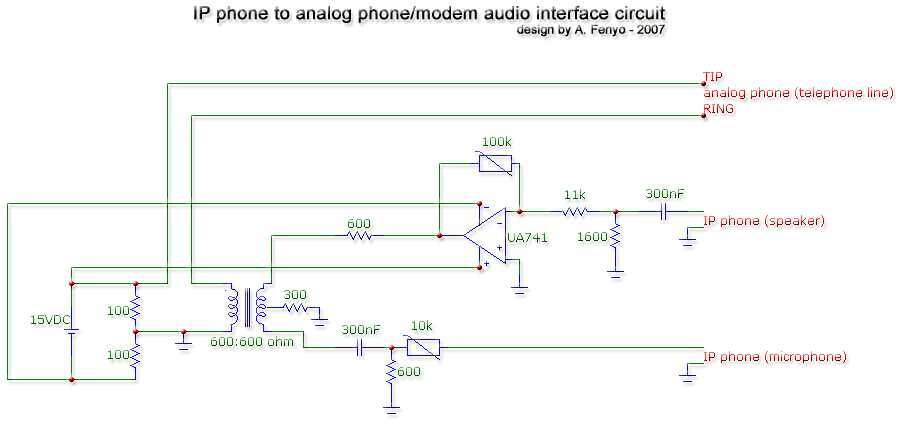
The transformer is a 600:600 ohm transformer, also referred to as a 1:1 ratio 600 ohm transformer. It has approximately the same number of turns on both the primary and secondary coils and is optimized for operation at a...