
Electric Fence circuit

The circuit design utilizes a C-MOS integrated circuit to control the ignition coil of a car, which is repurposed for use in an electric fence application. The primary function of the circuit is to produce high-voltage pulses that are necessary for delivering an effective electric shock to deter animals or intruders. The circuit is designed to operate efficiently with minimal power consumption, which is critical for battery-operated applications.
The average current draw of 20 µA to 85 µA indicates that the circuit is optimized for low power usage, allowing for extended battery life, which is vital for remote installations where regular battery replacement may not be feasible. The use of a 12-volt battery as the power source is recommended, with the inclusion of a trickle charger to ensure that the battery remains charged over time. A small solar panel can be integrated into the system for sustainable energy harvesting, although care must be taken with charging methods to prevent damage to the battery.
The ignition coil must be correctly connected to either the ground or the designated terminal to avoid overheating, which could pose safety risks. The circuit includes components such as capacitor C2 and variable resistor VR1, which are essential for pulse duration and frequency modulation, respectively. The optional LED indicator and resistor R4 serve as a visual confirmation of circuit operation, enhancing usability.
Proper assembly and maintenance of the circuit board are critical. It is important to remove all solder flux after assembly to prevent conductive paths that could lead to circuit failure, especially in humid conditions. Additionally, both the circuit board and coil should be adequately protected from environmental factors such as rain and snow, which could compromise the system's functionality. Insulators should be employed on the fence to prevent short circuits due to moisture, ensuring reliable operation of the electric fence system. An etched and drilled PCB is available for those interested in building this circuit, providing a solid foundation for assembly and performance.A circuit design, based on a C-mos chip to Drive a Car Ignition Coil. This is a Very Simple and Efficient Design for an Electric Fence. It puts out a Very high Voltage Current pulse, yet it draws a very small average Current from the battery or supply. As Accurate as I can Measure, the "AVERAGE Current Draw" varies between: 20 uA at at Slow Pulse setting to about 85 uA at the fast pulse setting.
So Battery life is "Really Good" and this makes a Good Electric Fence. Due to a High Peak Current Draw, this Fencer will NOT work properly, just running from a Power Adapter or a work-bench power supply. This Electric Fence Should be powered by a 12 Volt Battery and this battery. Should have a Trickle Charger on it. A Small "Solar Panal" would do this quite well. (Occassional Cycle Charging a car battery or Sealed lead acid Battery is not a good idea.) THE CASE OF THE COIL SHOULD BE CONNECTED TO EITHER GROUND OR THE DIST. TERMINAL. FAILURE TO DO SO, MAY RESULT IN THE CASE BECOMING ELECTRICALLY HOT. On Some Ignition Coils, the Points Terminal is Marked as "Dist" for Distributor and on some others it is marked as "Neg" or "-" C2 Determines the duration of the pulse and VR1 determines the number of pulses per second.
The Values shown give good Results. The LED and R4 are Optional. They just show its working. After assembly of the Circuit board, All Solder Flux Should be Removed from it. Solder Flux CAN Become Conductive in the presence of Moisture and this can result in eventual failure.Also both the "Circuit Board and Coil Must be Protected from Rain and Snow". Suitable Insulators must be used on the fence, or Rain will short it out. It Won't damage the circuit if that happens, But it also won't shock anything. Not much else I can say now, maybe more later. An Etched and drilled PCB's is Available from me. 🔗 External reference
Related Circuits
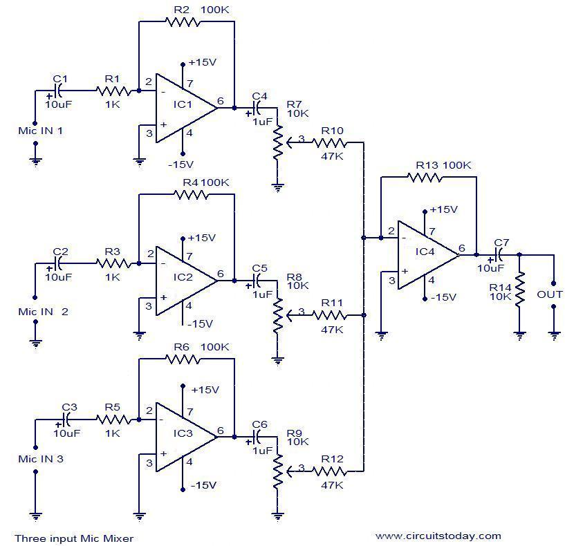
This document outlines a simple three-input microphone mixer circuit utilizing the widely used uA741 integrated circuits (ICs). Four uA741 ICs are employed in this design. IC1, IC2, and IC3 function as preamplifiers, each providing a gain of approximately 40...
Most homes today have at least a few infrared remote controls, whether for the television, video recorder, stereo, or other devices. Despite this, many individuals have experienced frustration when a light remains on after settling into a comfortable chair...
There are many individuals interested in listening to frequencies within the VHF range of 108 to 132 MHz. This VHF AM converter is designed to convert signals from a frequency band of 106 to 150 MHz, allowing users to...
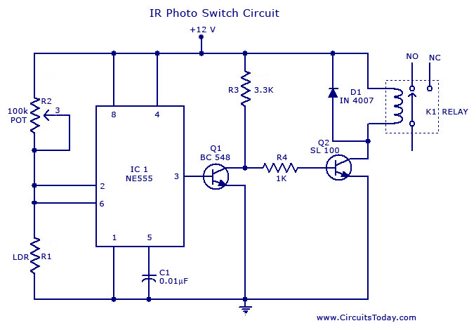
A simple photo switch circuit using an NE 555 IC with a diagram and schematic. This photo switch activates a relay when light intensity crosses a specified limit. It is a light sensor circuit suitable for home and industrial...
This hybrid circuit uses a mixture of transistors, an IC and a relay and is used to automatically open or close a pair of curtains. Using switch S3 also allows manual control, allowing for curtains to be left only...
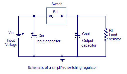
Switching regulators operate by drawing small amounts of energy from the input source and transferring it incrementally to the output. This is achieved using an electronic switch, which functions at a predetermined frequency, acting as a gate between the...