
Remote Doorbell Warning Switchs

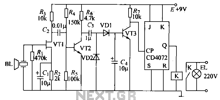
This circuit serves the dual purpose of auditory and visual notification of a doorbell press, enhancing the user experience in environments where the doorbell's sound may be masked by other noise, such as television or music. The design incorporates a series resistor (R1) to mitigate the additional load that a parallel lamp or LED would impose on the doorbell's power source. The selection of R1 is critical; it must be calibrated to allow sufficient voltage drop while ensuring that the doorbell mechanism remains operational.
In this configuration, the 22-ohm and 50-ohm resistors are strategically combined to achieve the desired resistance without compromising the doorbell's function. The parallel connection of these resistors effectively lowers the overall resistance seen by the doorbell, which helps maintain its operational integrity while allowing for the visual indicator to illuminate when the doorbell is activated.
The visual indicator, whether a traditional incandescent lamp or a more energy-efficient LED, provides a clear and immediate signal that someone is at the door. This can be particularly beneficial in households with individuals who are hard of hearing or in situations where the doorbell's sound may not be easily heard.
Overall, this circuit design exemplifies a practical solution to a common problem, utilizing basic electronic components to enhance the functionality of a standard doorbell system while considering energy efficiency and user convenience.The hardest part for this circuit was the title. It is quite easy to miss the sound of a doorbell if you are watching TV, this circuit gets round the problem by providing a visual indication, i. e. a lamp. As an alternative, a LED could also be used. You could just parallel a lamp across the doorbell, but this would mean extra drain from the doorb ell batteries or transformer. Using a series resistor R1 actually reduces current flow, and if run from batteries, will give them a longer life. The value of R1 is chosen so that about 0. 6 to 0. 7 volts is dropped across it, and the doorbell should still ring. I used a combination of a 22 ohm resistor in parallel with a 50 ohm. The doorbell still rang and circuit operated correctly. I used to have an electromechanical counter that registered each time when someone pressed the switch.
in fact, I remember a time when I had more "hits" at my doorbell then at my web site=:) 🔗 External reference
Related Circuits
The T-40-16 and 555 ultrasonic transmitter circuit configuration consists of an ultrasonic transmitter T-40-16 and a 555 timer circuit. By adjusting the potentiometer RP, the oscillation frequency of the circuit can be changed. The output pulse frequency from the...
This is a Doorbell Bird Voice Electro Suite designed to replace the old doorbell, providing a refreshing and exciting experience with a new doorbell system. The Doorbell Bird Voice Electro Suite is an innovative electronic circuit designed to enhance the...
This circuit enables the control of any equipment operating at 115 volts AC. It utilizes the Radio Shack infrared receiver module (MOD), part number 276-137, which can also be sourced from other suppliers listed on the Links page. The...

The miniature transmitter module, measuring 34 mm x 29 mm x 10 mm, is designed to operate all remote control receiver-switch combinations outlined in this project. A compact 9-volt PP3 battery can be utilized with the transmitter, which is...
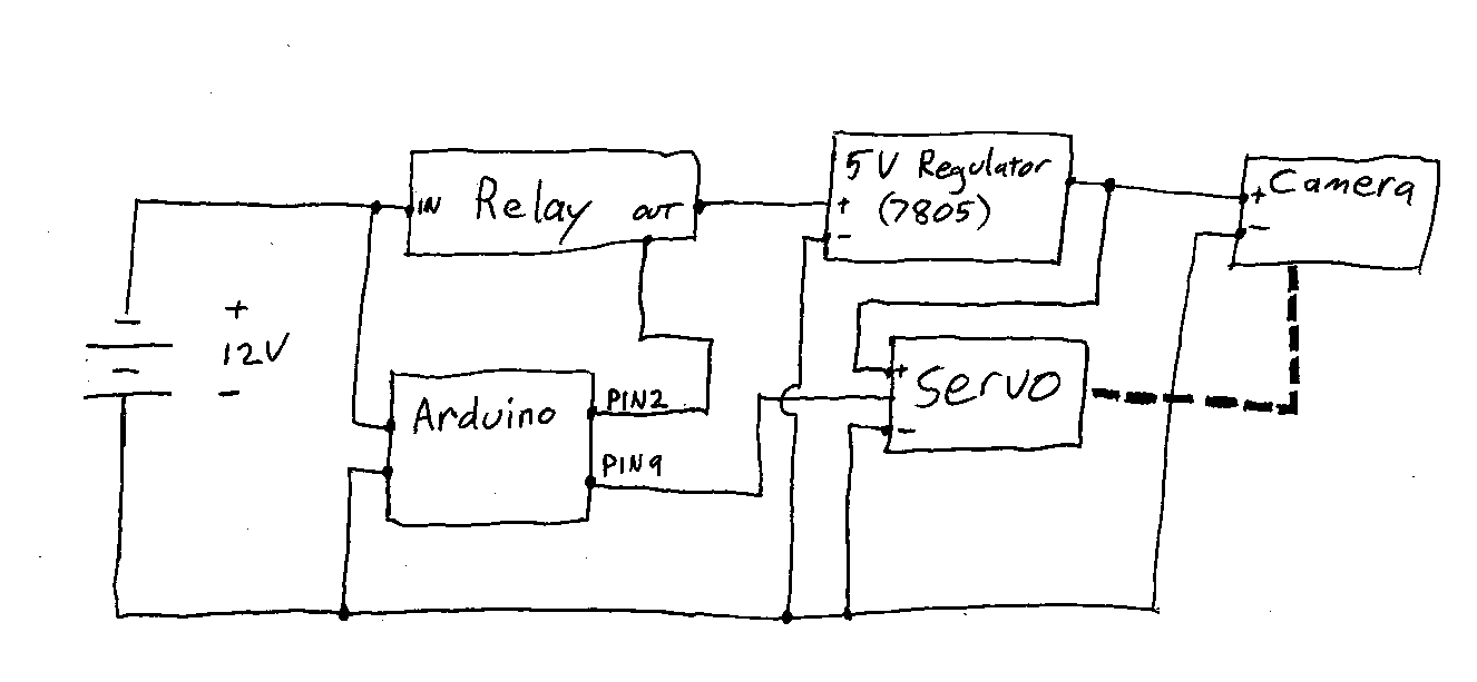
Information and resources on remotely using a DSLR camera, primarily utilizing Arduino-based solutions. The use of Arduino-based systems for remotely controlling DSLR cameras has gained popularity among photography enthusiasts and professionals seeking to enhance their shooting capabilities. These systems typically...
While developing an infrared (IR) extender circuit, a method was required to measure the relative intensities of different infrared light sources. This circuit is the culmination of that research. It utilizes a photodiode, specifically the SFH2030, as the infrared...