
DSLR Remote Control

The use of Arduino-based systems for remotely controlling DSLR cameras has gained popularity among photography enthusiasts and professionals seeking to enhance their shooting capabilities. These systems typically involve the integration of various components such as microcontrollers, relay modules, and camera control cables, allowing users to execute functions like shutter release, zoom control, and image capture remotely.
A common approach involves connecting an Arduino board to the DSLR's remote control port, which is usually a 2.5mm jack. The Arduino can be programmed to send signals to the camera, triggering the shutter at specified intervals or in response to external stimuli, such as motion detection or light changes. This setup can be particularly useful for time-lapse photography or wildlife photography, where the photographer may need to maintain a distance from the subject.
To implement such a system, the following components are typically required:
1. An Arduino board (e.g., Arduino Uno or Nano).
2. A compatible relay module to handle the camera's shutter control.
3. A 2.5mm stereo jack cable for connecting the Arduino to the DSLR.
4. Additional sensors or modules as needed for specific functionalities (e.g., PIR sensors for motion detection or light sensors).
The circuit design generally involves connecting the relay module to a digital output pin on the Arduino, with the relay controlling the connection to the camera's shutter release circuit. The Arduino is powered either through a USB connection or an external power source, depending on the application. Programming the Arduino involves writing code that defines the desired behavior, including timing for shutter releases and any additional logic for sensor integration.
Overall, Arduino-based solutions for remotely using DSLR cameras provide a flexible platform for photographers, enabling creative control over their equipment and facilitating a wide range of photographic techniques.Some links and info on remotely using a DSLR, mainly arduino-based 🔗 External reference
Related Circuits
Automatic fan control circuit. This circuit turns a 12V DC fan or CPU fan on or off based on temperature readings. The temperature can be adjusted using VR1. The automatic fan control circuit operates by monitoring the temperature of...
The aim of this project was to get a digital camera into a small electric radio controlled (RC) aeroplane and still have it fly. The aeroplane shown, a park flyer, weighs between 400 and 550 grams depending on the...
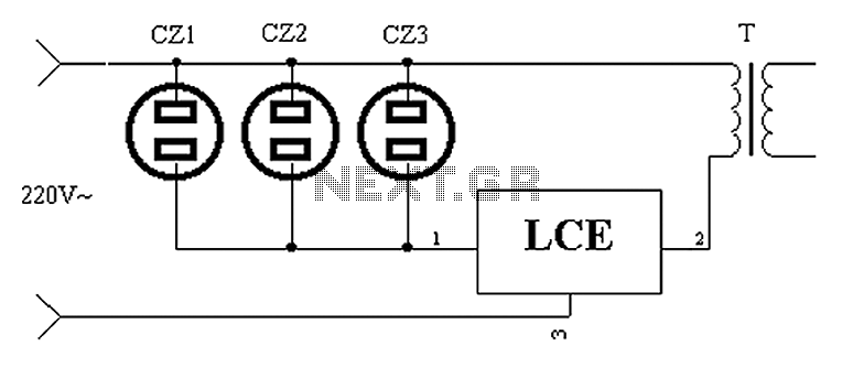
The application circuit operates as depicted below. It typically utilizes a shared TV antenna amplifier and an isolated power switch for the user. There are instances when the TV may not function, yet the antenna amplifier remains powered, leading...
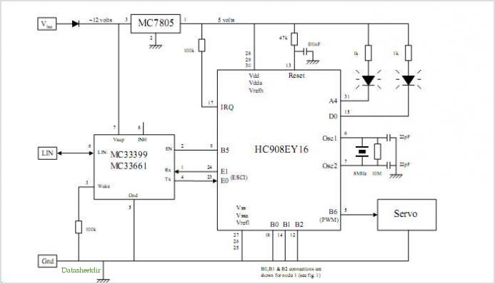
System Oscillator Crystal/Ceramic Oscillator. The following circuit combination of resistors, capacitors, and inductors depicts an equivalent circuit for a crystal or ceramic oscillator. The system oscillator, specifically a crystal or ceramic oscillator, utilizes a combination of passive components, including resistors,...
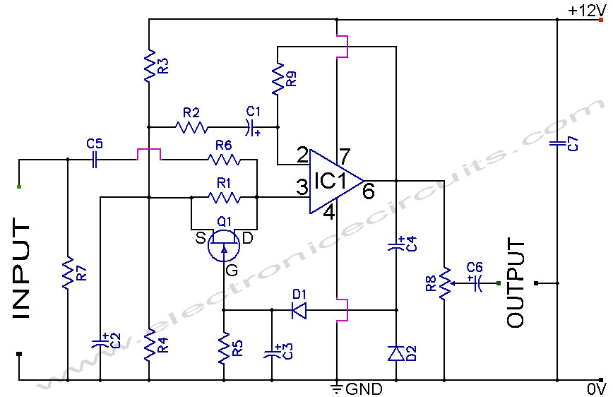
A section of the operational amplifier's output signal is rectified using 1N4148 diodes, followed by filtering, and is then directed to the gate of the FET input shunting circuit. As the output voltage increases, additional input shunting occurs, which...
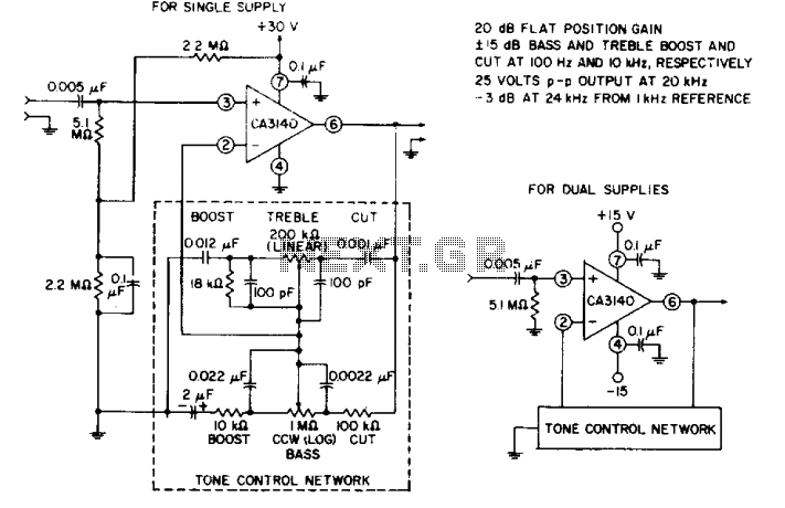
The circuit effectively utilizes the high slew rate, wide bandwidth, high input impedance, and high output voltage capability of the CA3140 BiMOS operational amplifier. The wideband gain of this circuit is equal to the ultimate boost or cut plus...