Remote Ignition System 100kv StunGun
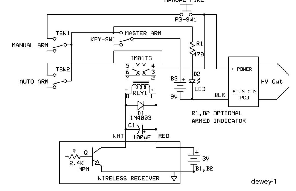
This is a straightforward guide on creating an economical remote or wireless ignition system for a spud gun or similar applications. It employs a doorbell circuit to transmit a radio frequency (RF) signal to activate a relay, which completes a 9V stun gun circuit, thereby powering it on. The total cost of materials is less than $20. The specific door chime receiver used in this guide is powered by two AA batteries in series, providing 3 volts. A voltmeter was utilized to measure the output when the door chime was activated, which also registered at 3V. If a voltmeter is not available, it is likely that the output will correspond to the circuitry voltage. It is important to determine the voltage supplied to the circuitry of the door chime receiver, as some operate at 3V while others may require higher voltages, such as 5V. Regardless of the voltage, any will suffice for this project. The first step involves cutting the two wires connected to the speaker. Following this, it is necessary to identify which wire is positive and which is negative by connecting them to an LED, voltmeter, or another electrical component capable of indicating polarity. Alternatively, the transistor located near one of the wire terminals can be examined; typically, the transistor is connected to the negative wire. The next step is to select the appropriate relay. A relay is an electrically operated switch that closes a circuit when a low-powered signal is sent to it, allowing the signal to continue to the rest of the circuit. In this application, the relay will complete the circuit for the stun gun. When a 9V supply is connected to the stun gun circuit, it should produce a continuous spark. However, by placing a relay between the 9V positive terminal and the stun gun positive terminal, the stun gun will remain inactive until the relay is triggered.
The circuit design incorporates a doorbell circuit, which functions as the remote transmitter. This circuit typically consists of a push button, an oscillator, and an RF transmitter module. When the button is pressed, the oscillator generates a signal that is transmitted via RF waves. The receiver, which is powered by two AA batteries, detects this signal and activates the relay.
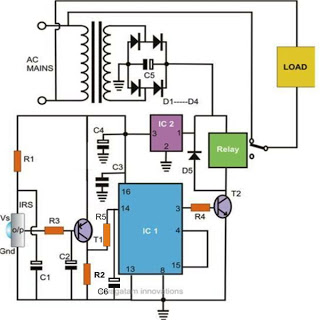
The relay chosen for this application should be rated for the voltage and current requirements of the stun gun circuit. A standard relay that can handle a 9V supply and the current drawn by the stun gun should suffice. The relay's coil is connected to the output of the doorbell receiver, while the relay's contacts are wired in series with the stun gun circuit.
Upon activation, the relay closes the circuit, allowing current to flow from the 9V battery to the stun gun, resulting in the desired sparking effect. It is crucial to ensure that the relay is rated appropriately to avoid damage or failure during operation.
Safety precautions should be taken when working with the stun gun circuit, as it can produce high voltage and current. Proper insulation and secure connections are essential to prevent accidental discharge or short circuits. Furthermore, testing the circuit with a multimeter before final assembly is recommended to ensure all components function correctly and to verify polarity and voltage levels.
Overall, this simple remote ignition system is a cost-effective solution for activating devices like spud guns, leveraging basic electronic components to achieve remote functionality.This is a simple how-to guide on making a cheap remote/wireless ignition for a spud gun or other application. It uses a doorbell circuit to transmit an RF signal to activate a relay that completes a 9V stun gun circuit, turning it on.
Can be made for less than $20. My particular door chime receiver was powered using two AA batteries in series, pro viding 3 volts. I used a voltmeter to measure the output when the door chime was activated and it too was 3V. If you don`t have a voltmeter, don`t worry as your output will probably match the circuitry voltage. Determine the voltage applied to the circuitry of your door chime receiver, some are 3V some may be higher like 5V. Doesn`t matter which voltage it is, any will do. First, you need to cut the two wires that are going to the speaker. Once that is done, determine which wire is positive and which is negative by connecting them to an LED, voltmeter or other electrical component that can tell you the polarity.
Another way is by finding the transistor near one of the wire terminals, it seems that the transistor is generally connected to the negative wire. Next, we need to determine which relay we need. The relay is an electrically operated switch, when a low powered signal is sent to a relay, it closes a switch and allows the signal to carry on to the rest of the circuit.
In this case, the relay will be completing the circuit of a stungun. When you attach a 9V to your stungun circuit, it should spark continuously but if we put a relay between the 9V positive terminal and the stungun positive terminal, the stungun can`t spark until the relay has been activated. 🔗 External reference
