
remote tester circuit

The remote tester circuit primarily consists of the TSOP1738 infrared receiver, which is sensitive to infrared signals emitted by remote controls. The TSOP1738 operates at a frequency of 38 kHz, making it suitable for most consumer remote control applications. The output of the TSOP1738 is connected to a microcontroller or a simple LED indicator.
When a remote control button is pressed, it emits infrared signals that are detected by the TSOP1738. The sensor converts these signals into electrical pulses, which can be processed further. If connected to a microcontroller, the output can be interpreted to indicate which button was pressed, allowing for detailed testing of the remote's functionality. Alternatively, when connected to an LED, the LED will illuminate to confirm that the infrared signal is being received.
The circuit can be powered by a standard 5V supply, which is commonly available in many electronic devices. Additional components may include resistors to limit current to the LED and capacitors for noise filtering, ensuring stable operation.
This simple yet effective remote tester circuit can be invaluable for troubleshooting and verifying the operational status of various remote controls, making it a useful tool for both technicians and hobbyists in the field of electronics.Here is a remote tester circuit or remote checker circuit which can be used to test TV and other remote controls. The circuit is very simple using only few components. The infrared sensor used in the circuit is TSOP1738. When the IR waves received by the infrared sensor it will make the 🔗 External reference
Related Circuits
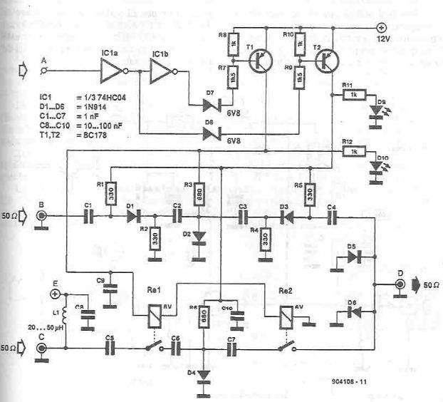
This antenna selector circuit diagram electronic project is constructed using standard electronic components and facilitates the switching between two FM antennas through a logic signal. The gates IC1b and IC1a manage the switching and interface between the required logic...
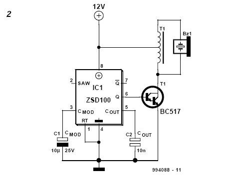
The DIY Electronic Siren circuit described here can produce three distinct US-style siren sounds: DIY police, DIY ambulance, and fire engine. The desired sound can be selected using switch S1. This circuit is suitable for use in toys (such...
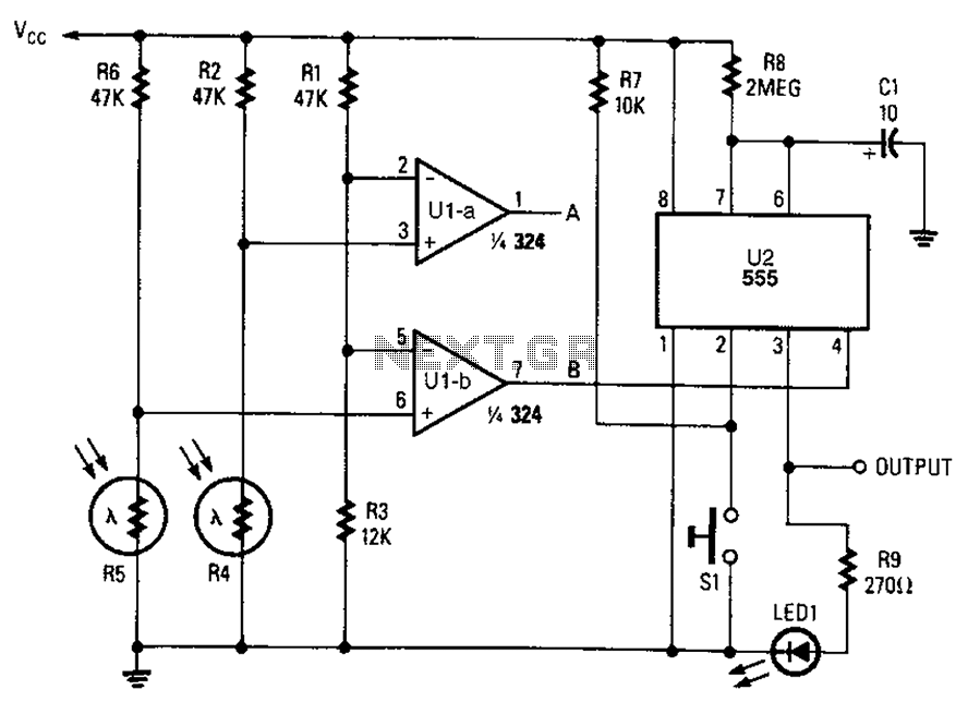
A combined monostable multivibrator using the 555 timer integrated circuit, along with a pair of light control comparators. This circuit can be utilized to control a load based on the timing parameters set within the circuit. The circuit comprises a...
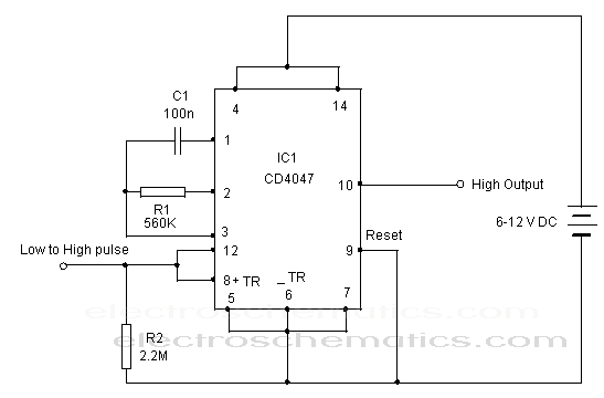
The CD 4047 is a low-power monostable and astable multivibrator that requires only an external capacitor and a resistor to produce output pulses. The CD 4047 integrated circuit (IC) is designed for generating precise timing pulses and can operate...
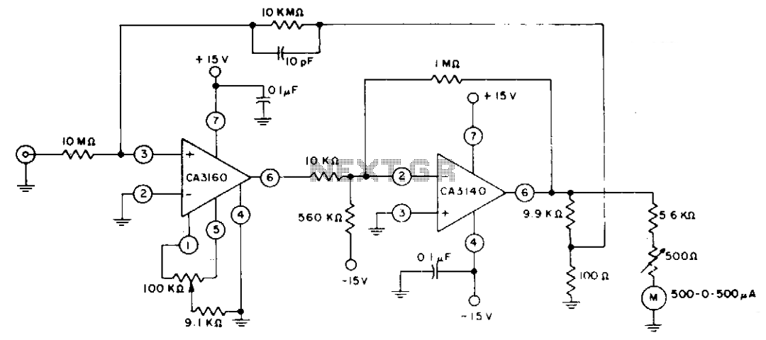
The circuit employs CA3160 and CA3140 BiMOS operational amplifiers to achieve a full-scale meter deflection of ±3 pA. The CA3140 functions as a 1T0 gain stage, supplying the necessary positive and negative output swing for the meter and the...
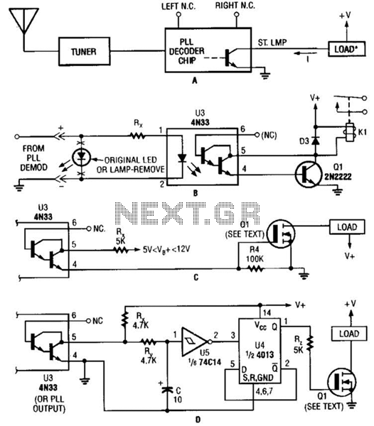
Several possible interface circuits are presented for use with a remote-control transmitter. The circuit labeled A demonstrates a typical FM stereo MUX decoder with a load connected directly to the open-collector output of a TA7343 PLL. The circuit labeled...