
repeating timer no4

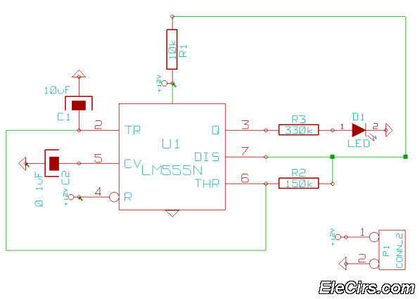
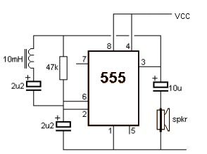
The circuit is designed to operate exclusively during nighttime conditions, making it suitable for applications such as outdoor lighting control or security systems that require activation only in low-light environments. The core component of this circuit is a light-dependent resistor (LDR), which changes its resistance based on ambient light levels. When the light intensity falls below a predetermined threshold, determined by the variable resistor, the circuit triggers its output.
The variable resistor, or preset, is crucial for calibrating the circuit's sensitivity to light. By adjusting this component, users can set the specific light level that will activate the timer. This adjustability ensures flexibility in various environments, allowing the circuit to function optimally under different conditions.
The output of the circuit can be connected to various devices, such as relays or transistors, which can control higher power loads. This feature enhances the circuit's versatility in real-world applications. For instance, it can be used to turn on garden lights automatically at dusk or activate security lights when it gets dark.
In summary, this circuit provides an efficient solution for controlling devices based on ambient light levels, with the added advantage of user-configurable settings for precise operation in varying light conditions.This circuit is the opposite of Repeating Timer No.3 . Its operation can be limited to the hours of darkness. Again - the variable resistor (preset) lets you choose the level of darkness at which the timer will begin to function.. 🔗 External reference
Related Circuits
The figure illustrates a preset outage timer circuit designed for an electric cooker. The timing range of the circuit extends from 1 hour to 12 hours, adjustable via a potentiometer (PR). The timing mode operates on a counting basis,...
This timer was designed primarily to switch off a portable radio after a set period. This feature allows users to fall asleep on the beach or in a hammock, knowing that the receiver will automatically turn off after a...
This is a very simple 555 timer circuit that serves as a straightforward theft deterrent, which may be just as effective. The idea is to have a flashing red LED indicate that your car is protected. This device can...
This circuit deactivates an amplifier or any connected device when a low-level audio signal at its input is absent for at least 15 minutes. By pressing P1, the device is powered on, supplying power to any appliance connected to...
A simple metal detector circuit can be implemented using a 555 timer chip. The schematic diagram illustrates that this project requires only a few external electronic components. The metal detector circuit utilizing a 555 timer operates in astable mode, generating...
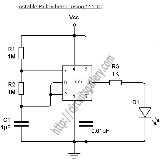
An astable multivibrator can be designed using a 555 timer IC, operational amplifiers, or transistors. The 555 timer IC provides accurate time delays ranging from milliseconds to hours, with the frequency of oscillation adjustable through simple modifications. This is...