
Repeating Timer No5

The temperature-controlled timer circuit employs a thermistor, which is a type of resistor whose resistance varies significantly with temperature changes. In this configuration, the thermistor is connected in a voltage divider arrangement with a fixed resistor, allowing the circuit to sense temperature variations effectively. The output from this arrangement is fed into a comparator or a microcontroller input, which determines if the thermistor's resistance has dropped below a predetermined level set by the preset potentiometer.
The preset potentiometer adjusts the reference voltage for the comparator, enabling customization of the temperature threshold. When the temperature exceeds the set point, the comparator triggers the timer circuit, activating the output device, which could be a relay or a transistor driving an external load.
The timer function can be realized using various components, such as a 555 timer IC configured in monostable mode, where the output remains high for a duration set by external resistors and capacitors. Alternatively, a microcontroller can be programmed to manage timing and control outputs based on temperature readings.
This circuit finds applications in temperature-sensitive environments, such as heating systems, temperature alarms, or automatic fan controls, where maintaining a specific temperature range is crucial. Proper layout and component selection are essential to ensure reliability and accuracy of the temperature sensing and timing functions.This circuit is a temperature controlled version of Repeating Timer No.3 . The light dependent resistor has been replaced by a temperature dependent resistor or thermistor. And a small preset potentiometer lets you choose the temperature above which the timer will operate 🔗 External reference
Related Circuits
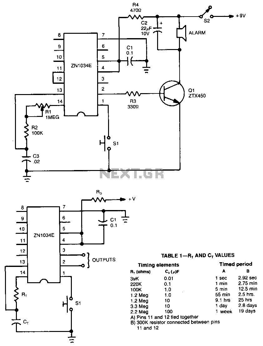
When used as a stand-alone device, the ZN1034E from Ferranti can provide timed intervals ranging from 1 second to 19 days, although the RC time constant is only 220 seconds. The ZN1034E includes an internal voltage regulator, an oscillator,...
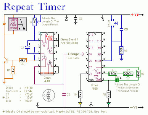
The following circuit illustrates a repeating interval timer circuit diagram utilizing the CMOS 4060 integrated circuit (IC). Features include its foundation on the CMOS 4060 IC and a 14-bit binary counter. The CMOS 4060 IC is a versatile component widely...
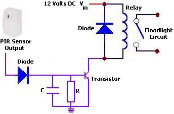
The circuit illustrates a 12V PIR sensor timer circuit diagram. Features include a 12 Volt DC supply, capable of activating a floodlight or other devices for a specified duration. The 12V PIR sensor timer circuit is designed to detect motion...
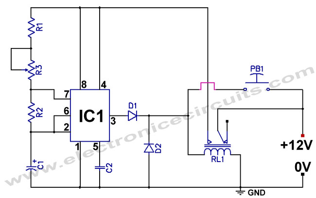
The standard 555 timer circuit consumes power from the battery even when the start push-button (PB1) is not pressed, due to a potential divider created by three 5kΩ resistors within the integrated circuit (IC). This power consumption, referred to...
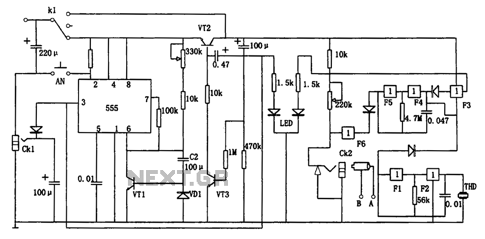
The circuit represents a general multi-function alarm and timing mechanism. Its timing capabilities range from 5 minutes to 3 hours. The timing components include C2, VD1, and VT1. The circuit utilizes a capacitance multiplier with a 555 timer. CK1,...
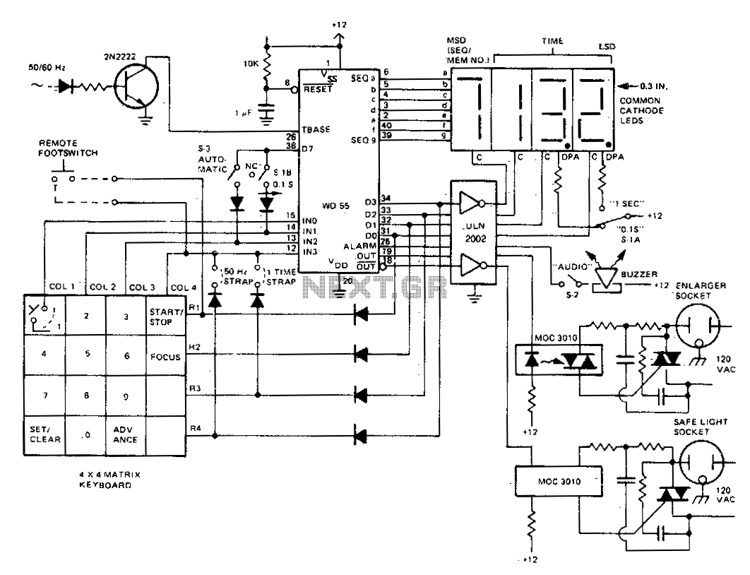
The darkroom timer/controller utilizes a minimal number of external components, including a display, a digit driver, a keyboard, and output switching devices. A 4-digit common-cathode LED display is preferred for use in darkroom settings. The time base is generated...