
Resistive neutral leakage protection circuit

The described voltage leakage protection circuit serves a critical function in safeguarding electrical systems from potential faults that could lead to dangerous leakage currents. The circuit employs a resistive element strategically placed to create an auxiliary neutral point, which helps in monitoring and managing voltage levels effectively.
In this configuration, the resistive element is selected based on its resistance value, which must align with the specific application requirements to ensure optimal performance. The power rating of the resistor is equally important, as it must be capable of dissipating the heat generated during operation without exceeding its thermal limits. This consideration is crucial to maintaining the reliability and longevity of the circuit.
The auxiliary neutral point created by the resistive element allows for the detection of any voltage discrepancies that may arise due to leakage currents. By monitoring the voltage at this point, the circuit can activate protective measures, such as disconnecting the load or triggering an alarm, thereby preventing potential hazards.
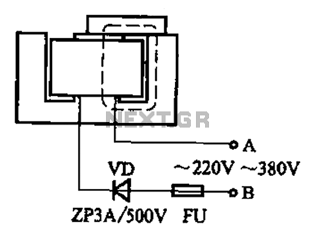
In summary, the resistive element in the voltage leakage protection circuit plays a vital role in enhancing the safety and reliability of electrical systems. Proper selection of resistance and power rating is fundamental to ensure the circuit functions as intended and provides effective protection against voltage leakage. By resistive element as an auxiliary neutral point voltage leakage protection circuit, as shown in FIG. Resistance selection should consider the resistance, power consistency r ate.
Related Circuits
It is advisable to prototype the entire circuit using a breadboard. This method simplifies the process significantly compared to attempting to determine the connections on a small printed circuit board. Prototyping a circuit on a breadboard allows for easy modifications...
The lamps are usually used as ballast or electronic ballast inverter. Here it is used to reduce voltage capacitor reactance. Interesting is also the method of ignition of the auxiliary electrodes involved over 150 Ohm resistors. To start simply...

The adjustable voltage monitor can be used to check whether the voltage in a circuit remains within a given range. If the DC voltage is less than the voltage at pin 5 of U1-B, then LED1 will light. If...
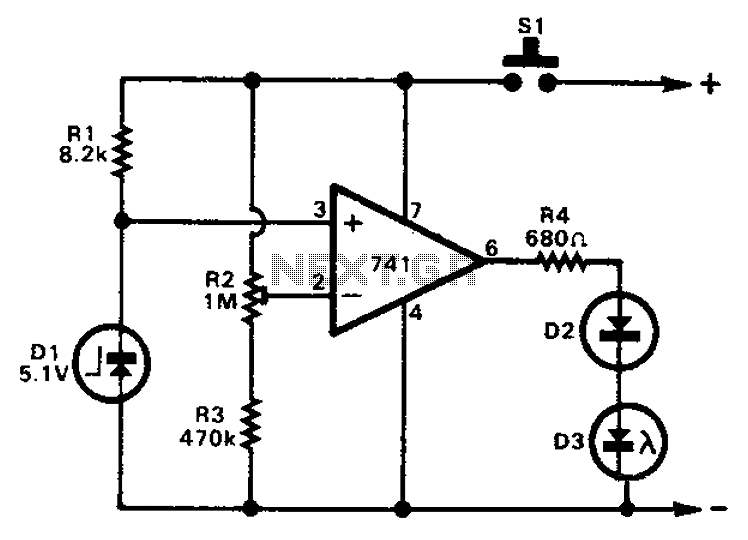
The 741 operational amplifier can function as a voltage comparator. It features a non-inverting input and a Zener-controlled voltage source, with a reference voltage set at 5.1V. Resistor R2 is used to adjust the in-phase input voltage to half...
After some minor loss of field magnets, they can be re-magnetized using a homemade method. A scrap of exchanges and contacts, as well as other models like CJ10-60 ~ 15, can be utilized. The circuit operates at 0A (compatible...
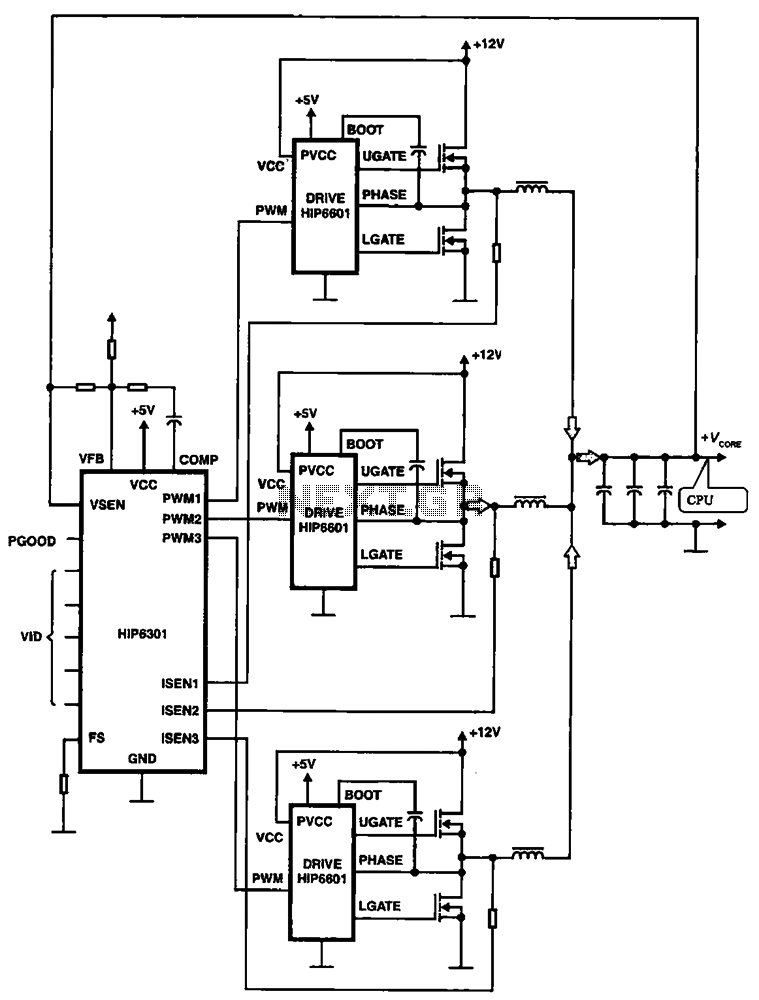
HIP6301 and HIP6601 are used in a 3-phase CPU power circuit. The HIP6301 and HIP6601 are integrated circuits designed for power management in CPU applications, particularly in multi-phase power supply systems. The HIP6301 is a high-performance synchronous buck controller,...