
reverse engineer a LED light bulb

The LED color-changing light bulb typically consists of several key components: a microcontroller, LED drivers, RGB LEDs, and a power supply circuit. The microcontroller serves as the central processing unit, controlling the timing and intensity of the LEDs. It may be programmed to produce various color patterns by adjusting the duty cycle of the PWM (Pulse Width Modulation) signals sent to the RGB LEDs.
The LED drivers are responsible for supplying the appropriate voltage and current to the LEDs, ensuring they operate within safe limits. Often, these drivers include constant current sources to prevent damage due to thermal runaway. The RGB LEDs are arranged in a way that allows for the mixing of red, green, and blue light to create a wide spectrum of colors.
The power supply circuit typically consists of a rectifier, filter capacitors, and a voltage regulator. This section converts the AC mains voltage to a lower DC voltage suitable for the microcontroller and LED drivers. Additionally, safety features such as fuses or circuit breakers may be included to protect against overcurrent conditions.
To further understand the remaining mysteries of the circuit, it may be beneficial to analyze the communication protocols used (if any), such as I2C or SPI, which could be employed for remote control or synchronization with other devices. Additionally, examining the thermal management aspects, such as heat sinks or thermal pads, is crucial for ensuring long-term reliability and performance of the LED bulb.
Overall, thorough analysis of the circuit layout and component specifications will aid in uncovering the remaining unknowns associated with the LED color-changing light bulb.Almost a month ago I started trying to reverse engineer an inexpensive LED color changing light bulb. With your help I`ve mapped out the circuit, and taken control of the bulb. But there`s still a few mysteries in this little blinker.. 🔗 External reference
Related Circuits
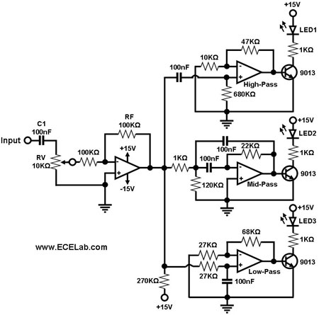
The simple circuit for converting an audio signal. The circuit basically consists of a buffer/amplifier stage and three filter circuits. The audio signal conversion circuit is designed to process audio signals efficiently while maintaining signal integrity. The circuit architecture includes...

To control 40 LEDs using a single PIC 18F2455 microcontroller, the LEDs were organized into a configuration of four columns, each containing 10 rows of LEDs. Each LED in a column was connected to a separate pin on the...
Designs for audio amplifiers with DC coupling to the load are not frequently seen today, despite offering distinct advantages. Audio amplifiers that employ DC coupling to the load provide several benefits that can enhance performance in specific applications. In traditional...
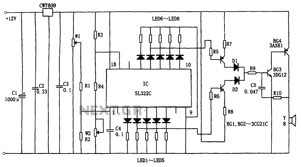
The circuit illustrated in the figure is a hydraulic oil level alarm system for automotive applications. It consists of a light-emitting diode (LED) driver, the SL322C integrated circuit (IC), a voltage regulator circuit (CW7809), and hydraulic oil level sensors...
The following touch switch circuit utilizes a CA3240 dual BiMOS operational amplifier to detect small currents flowing between the contact points on a touch plate. The touch switch circuit employs a CA3240 dual BiMOS op-amp, which is known for...
This circuit enables car headlights to flash on and off simultaneously or alternately. It is based on the 555 timer operating in astable mode. The output of the 555 timer will go high for an adjustable period and then...