
RF Decibel Meter

The zine serves as a comprehensive resource for individuals interested in electronics, providing a wide array of circuit diagrams that illustrate various electronic components and their interconnections. It includes detailed DIY projects that empower users to build their own electronic devices, fostering hands-on learning and experimentation. Each project is designed to cater to different skill levels, from beginners to advanced practitioners, ensuring accessibility for all.
In addition to practical projects, the zine offers electrical data sheets that provide essential specifications and characteristics of various electronic components. This information is crucial for understanding component behavior and selecting the right parts for specific applications. Furthermore, the inclusion of microcontroller projects highlights the growing importance of programmable devices in modern electronics, offering insights into coding and interfacing techniques.
Overall, this zine is an invaluable tool for anyone involved in the electronics field, whether for educational purposes, professional development, or personal interest. It encourages creativity and innovation while providing the foundational knowledge necessary to navigate the complexities of electronic design and implementation.This is a zine dedicated to electronics circuit diagrams, diy (do it yourself) electronics projects, electrical electronics data sheets, and micro controller projects for hobbyist, students, consultants and product designers. 🔗 External reference
Related Circuits
This circuit provides a simple visual indication of audio level signals, adaptable to various user requirements. It can be configured for different input levels, which can be adjusted using trimmer potentiometers TR1 (state) and TR2 (gain). The audio signals...
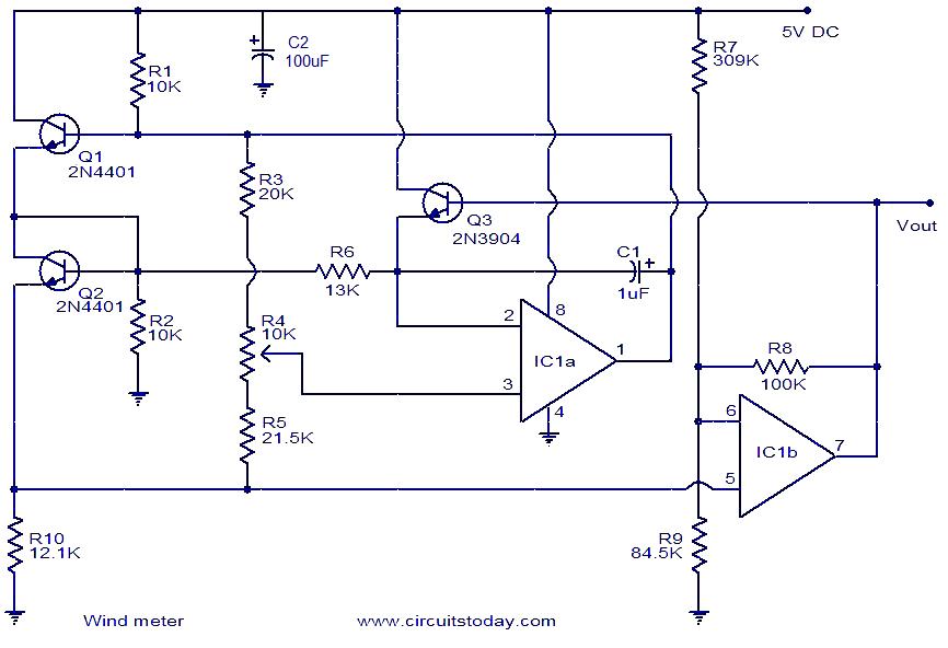
This is a simple wind meter (anemometer) circuit. While accuracy cannot be guaranteed, the circuit functions adequately. It can measure wind speeds up to 75 m/s. Transistors Q1 and Q2 are employed for wind sensing, utilizing the relationship between...
Most analog multimeters are capable of measuring resistance over a wide range of values, but they can be inconvenient to use due to the reverse reading scale, which is also non-linear. Analog multimeters, often referred to as VOMs (Volt-Ohm-Milliammeter), are...
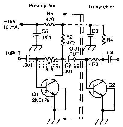
This simple, inexpensive, wideband RF amplifier provides 14 dB gain on two meters without the use of tuned circuits. The RF amplifier described operates within the two-meter band, which typically spans frequencies from 144 to 148 MHz. It is designed...
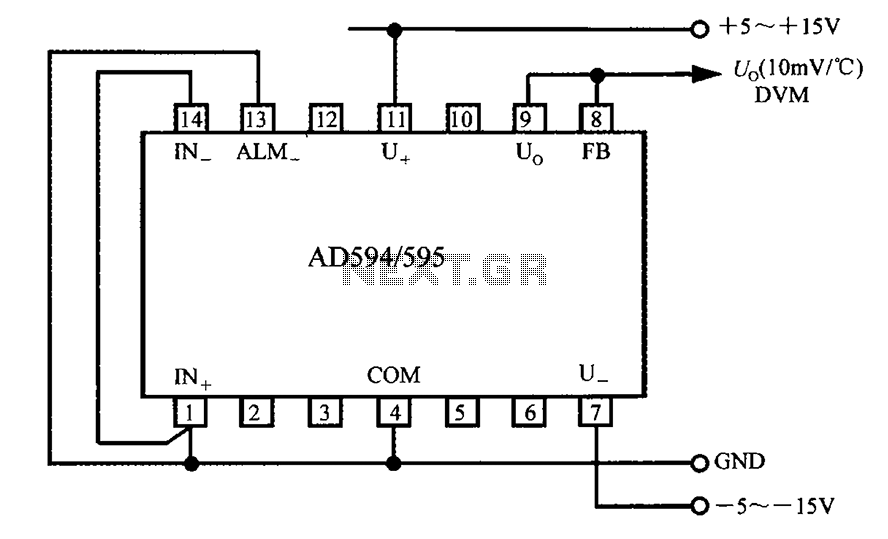
The AD594/595 can be configured to measure temperature in Celsius. In the circuit diagram, the IN+ and IN- terminals should be shorted to the COM terminal. The output voltage (Uo) has a temperature coefficient of 10 mV/°C, which can...
The frequency formula of a 555 oscillator is well-known. For given resistors and capacitors, the frequency can be calculated using a specific formula derived from mathematical principles. The 555 timer IC is widely used in various applications, including oscillators, timers,...