
RF Isolator

An RF isolator, also known as a directional coupler, is a critical component in radio frequency applications, particularly in testing and measurement setups. The primary function of an RF isolator is to ensure that signals can only flow in one direction, effectively preventing reflections and potential damage to sensitive equipment. This is achieved through the use of non-linear ferrite materials that exhibit unique magnetic properties when exposed to high-frequency signals.
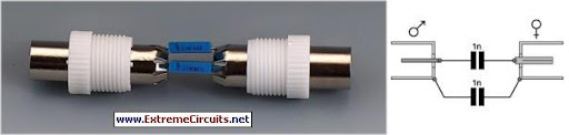
In a typical RF isolator circuit, there are three main ports: the input port, the test port, and the output port. The input port is where the RF signal is introduced, typically from a test generator. The test port is connected to the device under test (DUT) or an antenna, while the output port is linked to a signal level monitor or any other measurement device. The isolator's design ensures that signals traveling from the input to the test port are transmitted effectively, while any signals attempting to travel in the reverse direction from the test port to the input port are attenuated.
The operational principle of the RF isolator relies on the interaction of the RF signal with the ferrite material, which is often placed within a magnetic field. When a signal enters the isolator, the ferrite material's non-linear characteristics allow it to pass through in the intended direction. However, if a signal attempts to return from the test port to the input port, the ferrite's properties cause it to be absorbed or reflected, thus protecting the input circuitry.
For optimal performance, the test port is typically terminated with a 50-ohm load, which is a standard impedance in RF applications. This termination allows for maximum power transfer and minimizes reflections, ensuring that the isolator operates effectively without introducing additional losses. The design of RF isolators can vary, but they are often housed in compact enclosures to facilitate integration into larger systems.
Overall, the RF isolator is an essential component for ensuring signal integrity in high-frequency applications, making it invaluable in laboratory settings, telecommunications, and various RF engineering tasks.An RF isolator is a seemingly magic device that allows signals to pass in only one direction. Signals applied to the input port are sent to the test port and signals coming into the test port can only go to the output port. This one-way property is usually accomplished with special non-linear ferrite/magnet structures operating at very high frequencies.
For a typical setup the test generator is connected to the input port, the antenna or device to be tested is connected to the test port, and a signal level monitor is connected to the output port. When the test port is terminated with 50 ohms, no energy 🔗 External reference
Related Circuits
Nowadays, many audio-visual devices in homes are interconnected. This is particularly true for televisions, which may connect to DVD players, hard disk recorders, surround-sound receivers, and often PCs. This interconnection can lead to issues such as ground loops in...
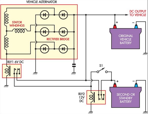
This circuit is straightforward and utilizes a 6V supply from one of the stator connections of the vehicle's alternator. This supply is connected to a 6V automotive relay (RLY1), which controls a Continuous Duty Solenoid (RLY2). The solenoid serves...
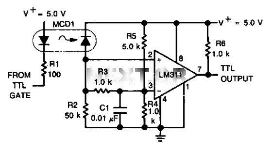
An optoelectronics device is utilized to couple a digital (TTL) signal to another system. The photodiode within the optocoupler drives an LM311 configured to generate a TTL-compatible output. This configuration is particularly beneficial in scenarios where grounds cannot be...
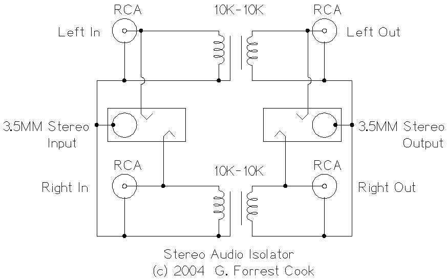
This circuit is useful for removing ground loop hum on a remote line level audio signal line. It can be used to connect a computer sound card to a stereo amplifier's line input. Other uses include tapping into a...
A ringer interface circuit is designed to buffer the output of a central telephone system, which connects to multiple ringers distributed throughout a building. This circuit addresses an issue where the line overloads when ringing, requiring a reset. The...

The circuit protects a solid-state relay from overloads by limiting current, automatically disconnecting the load after detecting a short circuit, and generating a fault-condition output signal. During normal operation, the controlling unit sets the flip-flop, IC1, which activates transistor...