
rf module interfacing with spartan 3an fpga

The RF module described operates within the specified frequency range and utilizes Amplitude Shift Keying (ASK) for modulation. The Spartan-3an board serves as a platform for integrating this RF module, which is designed to facilitate wireless communication. The RF transmitter and receiver pair operates efficiently at a frequency of 434 MHz, making it suitable for various applications requiring short-range communication.
The RF transmitter is responsible for converting serial data into RF signals. It employs an antenna connected to pin 4 to radiate the modulated signal, achieving data rates between 1 Kbps and 10 Kbps. This range is adequate for many low-bandwidth applications, such as remote controls, wireless sensor networks, and telemetry systems.
On the receiving end, the RF receiver captures the transmitted RF signals and demodulates them back into serial data. This process ensures that the original data is accurately retrieved. The encoder and decoder play crucial roles in this communication system, as the encoder prepares the data for transmission by converting it from parallel to serial format, while the decoder reverses this process upon reception, ensuring that the data is correctly interpreted by the receiving system.
The integration with the FPGA I/O lines allows for flexibility in managing and processing the data, enabling developers to implement custom logic and control mechanisms tailored to specific applications. Overall, this RF module setup provides a robust solution for wireless data transmission, leveraging the capabilities of the Spartan-3an board and the efficiency of ASK modulation.The RF module, as the name suggests, operates at Radio Frequency. The corresponding frequency range varies between 30 kHz & 300 GHz. In this RF system, the digital data is represented as variations in the amplitude of carrier wave. This kind of modulation is known as Amplitude Shift Keying (ASK). The Spartan-3an board has external RF Module interf acing, indicated as in Figure. This RF module comprises of an RF Transmitter and an RF Receiver. The transmitter/ receiver (Tx/Rx) pair operates at a frequency of 434 MHz. An RF transmitter receives serial data and transmits it wirelessly through RF through its antenna connected at pin4 at the rate of 1Kbps - 10Kbps. The transmitted data is received by an RF receiver operating at the same frequency as that of the transmitter.
The encoder is used for encoding parallel data for transmission feed while reception is decoded by a decoder. Finally connected with FPGA I/O lines. 🔗 External reference
Related Circuits
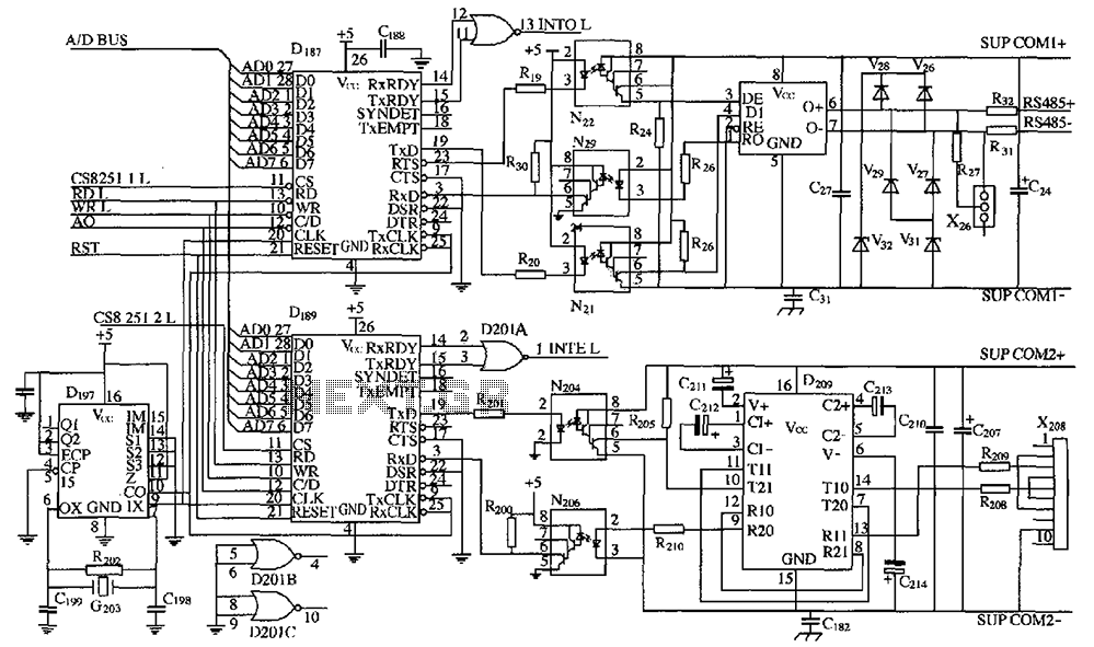
As shown in the figure, D187 is a universal asynchronous receiver-transmitter (UART). Its RX/TX signals are received through optocouplers N21, N22, and N29, facilitating RS-485 communication. The interface receiver/transmitter D28 and microprocessor D211 are completely optically isolated. D197 serves...
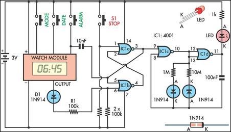
This device serves as a daily medication reminder. It incorporates a crystal watch and a 4001 quad 2-input NOR gate, with two of the gates (IC1a and IC1b) configured as an RS flip-flop. The watch is programmed to signal...
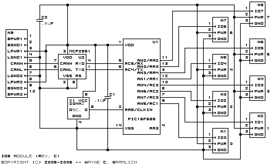
The bus is connected to the 2G-5 shrouded connector N9. The two CAN bus signals are routed to the PCP2551 CAN bus transceiver U2. The output from U2 is directed to the UART transmit and receive signals on the...
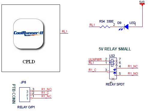
The CoolRunner-II board features external 5V relay interfacing, as indicated in the accompanying figure. The ULN2803 is utilized as a driver for the CPLD I/O lines, with the driver outputs connected to the relay modules. A PTB connector is...

An 8051 program must interact with external devices that facilitate communication with users. One of the most prevalent devices connected to an 8051 microcontroller is an LCD display. Common types of LCDs used with the 8051 include 16x2 and...
If a sensor is resistive, an alternating current (AC) is equivalent to pulsed direct current (DC), and the sensor will degrade based on the root mean square (RMS) value of the AC signal. Applying 1V AC RMS is effectively...