
TV signal amplifying circuit diagram conversion

The described circuit employs an amplification system designed to enhance the video output signals from devices like VCRs and DVD players. These devices typically produce signals that may be too weak for effective transmission or display on larger screens. The amplification process boosts these signals, ensuring that the output is strong enough for clear viewing.
In addition to video amplification, the circuit also features a radio frequency (RF) transmission capability. This allows the amplified signals to be transmitted wirelessly over a radius of approximately 7 meters. Such functionality is particularly advantageous in home entertainment setups, where it enables users to enjoy their content without the constraints of physical connections between devices.
The schematic design would typically include components such as operational amplifiers (op-amps) for signal amplification, RF modulators for converting the amplified video signals into RF signals, and antennas for effective transmission. Power supply considerations must also be addressed to ensure that the amplification circuits operate within their specified voltage and current ranges.
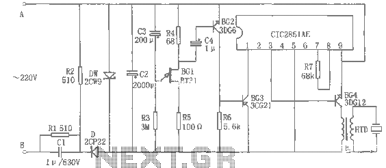
Overall, this circuit design not only addresses the need for signal amplification but also incorporates wireless transmission capabilities, making it suitable for modern multimedia applications. As shown in FIG amplification is used to convert a variety of devices and TV video output signal, such as some VCRs, DVD players need weak output signal amplification occasions , it can open the radio frequency signal is transmitted to about 7m radius, for more while watching TV.
Related Circuits
Video-DVM is a very cheap DVM that shows how an output as complex as a videocomposite signal can be generated entirely in software: two I/O pins and three resistors are all the hardware required. Connected to any TV set...
The rice cooker notification circuit operates as follows: When the rice cooker is in operation, both terminals A and B have a voltage of 0, meaning the entire circuit remains inactive. In the event that the rice cooker runs...

A LAN tester circuit diagram is presented in two designs. The first design utilizes a timer IC 555 and a decade counter 4017. The second design employs a microcontroller ATtiny2313. The first design of the LAN tester circuit incorporates the...
This is a solar tracking circuit designed to harness power from sunlight. The circuit operates optimally by maximizing sunlight exposure to generate electricity. The solar tracking circuit utilizes a combination of photovoltaic (PV) cells, sensors, and a microcontroller to adjust...
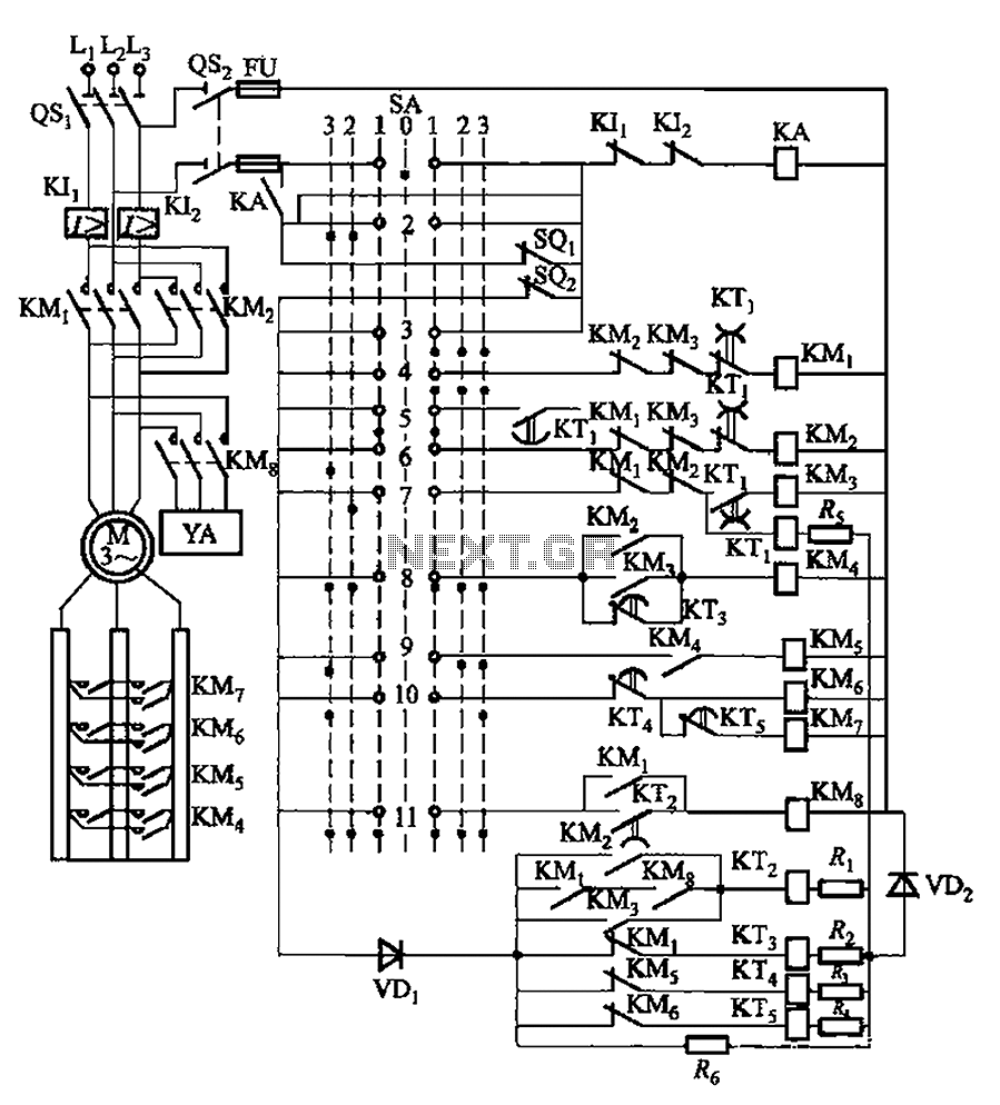
The system involves a master controller and a PQS1 Series Magnetic control panel, which includes a control circuit designed to manage the bridge crane hoist lifting mechanism. The master controller handle SA features seven positions: alongside the zero position,...
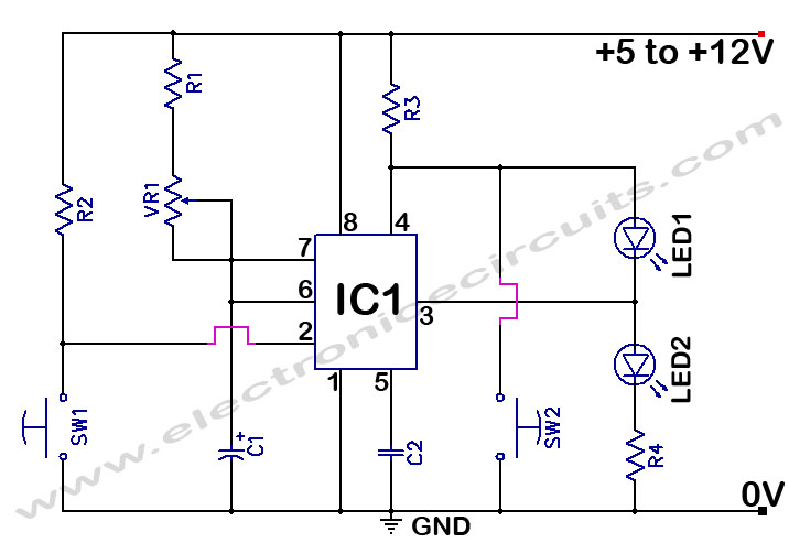
The 555 Timer Time Delay Circuit uses LEDs to visually indicate the status of the circuit at any moment. The operation begins when the reset switch, SW2, is activated. The 555 Timer is a versatile integrated circuit widely used for...