
Stepper Motor Controller

The motion-controlled photography rig requires precise control over the stepper motors, which are crucial for achieving accurate and smooth movements during photography sessions. The L298N dual full-bridge motor driver is selected for its capability to handle the necessary inductive loads while allowing for bi-directional control of the motors. This driver can effectively manage the stepper motor's phases by controlling the four inputs, which correspond to the outputs that drive the motor coils.
The selected capacitors serve to stabilize the power supply, ensuring that any fluctuations in voltage due to sudden changes in current draw by the motors do not adversely affect the operation of the driver or the performance of the motors. This is particularly important in applications where precise timing and control are critical, such as in motion-controlled photography.
The inclusion of resistors for current measurement allows for monitoring the performance of the motors, which can help in assessing their operational efficiency. Although these resistors are not strictly necessary, they provide valuable feedback for troubleshooting and optimization of the system.
The fast recovery diodes are essential for protecting the L298N from potential damage caused by back-EMF generated when the motors are de-energized. This is a common concern in inductive circuits, and the use of diodes ensures that the energy does not flow back into the driver, which could lead to failure of the components.
Overall, the design incorporates essential components that contribute to the reliability and functionality of the motion-controlled photography rig, ensuring that the system operates smoothly and efficiently for capturing high-quality images.I`ve managed to complete the first phase of my motion-controlled photography rig: setting up a pair of bipolar stepper motor controllers. This is the most important non-mechanical part of the project, as without control of motors there can be no awesome-tastic motion.
I went over some preliminary planning in my first MoCo-related post, but I`ll go through my list of materials again as well as the general process of building and operating the controller in this post. And if you need a refresher on stepper motors well blah. To start out, I purchased an L298N dual full bridge motor driver. Another option would be to use an SN7544 H-Bridge, as demonstrated on the Arduino site. However, I couldn`t find a wiring schematic for that particular implementation that included back-EMF protection diodes.
Regardless, both IC`s are designed to power inductive loads (like a motor) and allow you to do bi-directional rotation on a DC motor, or control a stepper motor. The only problem with the L298N is that it comes in a 15-lead Multiwatt package, aka something you can`t plug into a breadboard.
Sparkfun sells a breakout board for $3 intended specifically for this IC but that costs more than the chip itself, so I opted to skip it and work out my own ridiculous wiring methodology. The L298N functions basically as such: It has 4 inputs and 4 outputs. Each input corresponds to an output, and by powering these pins in a specific sequence, you can advance a stepper motor (see Wikipedia picture below).
There are variations on the 1-2-3-4 stepping scheme, like 12-23-34-41, that increase torque by engaging more coils of the motor but they complicate the wiring and also the control. Apparently one drawback is that it does not guarantee absolute position as well as the 1-2-3-4 scheme does (do correct me if I`m wrong).
If you take a look at the L298 schematic for a stepper motor (see snippet above), you`ll notice a few other bits of analog fun, some capacitors, some resistors, and some diodes. I used 0. 1uF 50V 105C radial electrolytic capacitors, which serve the purpose of power-conditioning your source voltage.
Should there ever be a sudden spike in power consumption that a battery can`t keep up with (like if you power up the stepper motor), the capacitors will help you out until your power supply has steadied out (we`re talking no longer than a millisecond here). If you`re using a bench power supply, then the capacitors probably aren`t as essential. 1 OHM 1W 1% metal film resistors are for the express purpose of giving you a voltage drop to measure, should you desire to know how much current your motors are drawing.
If you don`t care, then I`m pretty sure you can skip the resistors. It shouldn`t matter. Lastly, 1N4937 600V 1A fast recovery diodes were used in order to keep the stepper motors from regurgitating electricity back into the L298N. For those of you that don`t know, inductors (or any coils of wire) act like pitchers or water. If you put a current through an inductor, it`s like stirring the pitcher with a spoon. If you suddenly stop, the water wants to keep moving. This behavior makes inductors potentially damaging to circuits if they are of sufficient size er inductance.
Diodes are one-way-valves that prevent electricity from spilling back out of the stepper motors once you have ceased putting energy into its coils. I purchased all of these parts from Tayda Electronics, and I mention this not to shamelessly promote them, but because they are much cheaper than Sparkfun and the like for raw materials.
Even with shipping prices, which can be waived with a timely coupon code from their Facebook page, you can buy materials for 4 motor controllers for the price of one pre-built one. AND, you`ll learn something making it instead of buying pre-fab circuit boards Now, everything I mentioned abo
🔗 External reference
Related Circuits

Usually we see Digital clock on LCD or 7 segment. But, this AVR Digital Clock which is designed by Ficara Emilio displayed on Oscilloscope. The project uses ATtiny 2313 as the main controller. What an interesting microcontroller project. Source...
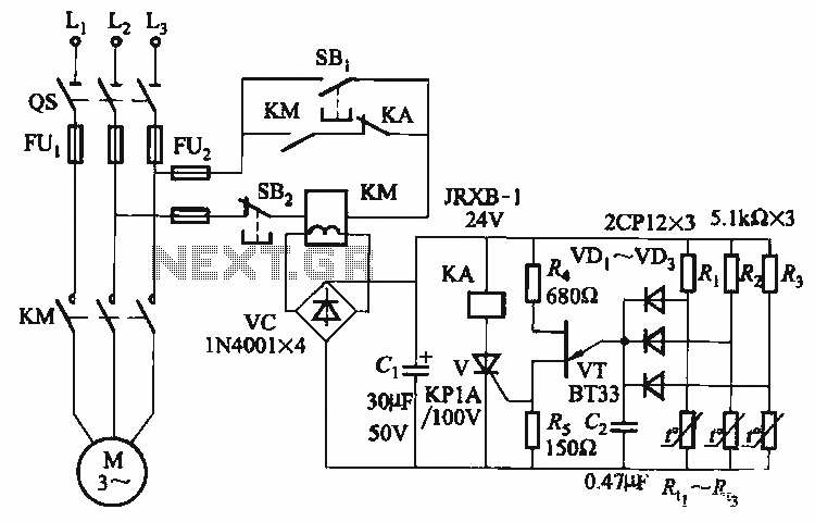
The thyristor control circuit includes a bridge circuit designed to regulate the temperature in the contactor coil KM, along with a secondary winding that functions as a power protection device. It comprises a thermistor (R:., Rt3) and a resistor...
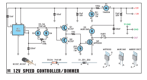
This circuit can function as a speed controller for a 12V motor with a continuous rating of up to 5A or as a dimmer for a 12V halogen or standard incandescent light. The circuit utilizes a pulse-width modulation (PWM) technique...
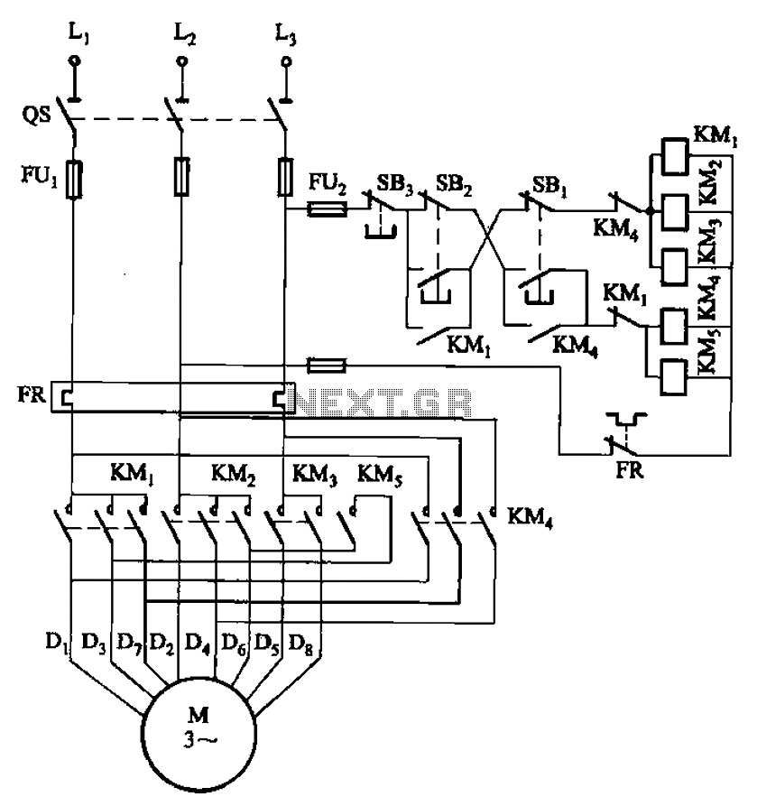
The circuit illustrated in Figure 3-104 features SB2, which functions as the low-speed operation button, and SBi, which serves as the high-speed operation button. The circuit design utilizes two distinct operational buttons, SB2 and SBi, to control the speed of...
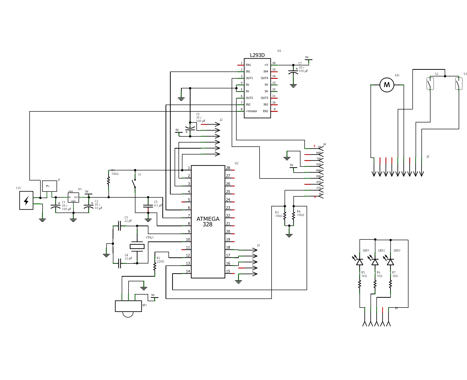
The project is "Motorized Curtain" with Remote control. It is made up of MCU ATMEGA328 with Arduino BootLoader, motor driver L293D (I used L293B with external diodes, because I couldn't find L293D), IR Receiver TSOP 1738, DC Motor from...
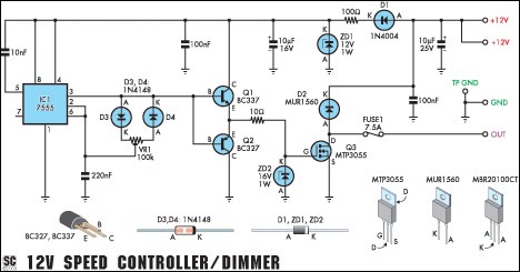
This circuit serves as a speed controller for a 12V motor with a continuous rating of up to 5A or as a dimmer for a 12V halogen or standard incandescent lamp rated up to 50W. It regulates power to...