
Potentiometric voltmeter

Construct the two-resistor voltage divider circuit as shown in the schematic diagram and illustration. If the two high-value resistors are of equal value, the battery's voltage should be divided in half, with approximately 3 volts dropped across each resistor. Measure the battery voltage directly with a voltmeter, then measure the voltage drop across each resistor. An unusual observation may be noted in the voltmeter's readings. Normally, series voltage drops should equal the total applied voltage, but a significant discrepancy may be observed. This is not a violation of Kirchhoff's Voltage Law. The explanation is that connecting a voltmeter across either resistor alters the circuit, resulting in a voltage reading that differs from the scenario without the meter connected. An analogy can be drawn to an air pressure gauge used to check a pneumatic tire's pressure; when the gauge is connected, it releases some air, affecting the pressure reading. In a similar manner, voltmeters influence the voltage they measure by bypassing some current around the component whose voltage drop is being measured. Although this effect is typically negligible, it becomes pronounced in this circuit.
To further investigate, replace the two high-value resistors with two 100 kΩ resistors and repeat the experiment. Then, replace those resistors with two 10 kΩ units and observe any changes in the voltage readings. This will provide insight into the voltmeter's impact on a circuit concerning the circuit's resistance. Ensure that any low-value resistors are replaced with the original high-value (≥ 1 MΩ) resistors before proceeding. Measure the voltage across the two high-value resistors one at a time using a digital voltmeter instead of an analog voltmeter. Notable differences may be observed between the readings of the digital and analog meters. Digital voltmeters typically exhibit higher internal (probe-to-probe) resistance, resulting in lower current draw compared to an analog voltmeter when measuring the same voltage source. An ideal voltmeter would draw no current from the circuit under test, thereby avoiding voltage impact issues. If two voltmeters are available, connect one across one resistor and the other across the second resistor. In this case, the voltage readings should add up to the total voltage, indicating a more accurate measurement.The potentiometer value is not critical: anything from 1 k © to 100 k © is acceptable. If you have built the "precision potentiometer" described earlier in this chapter, it is recommended that you use it in this experiment. Likewise, the actual values of the resistors are not critical. In this particular experiment, the greater the value, the bett er the results. They need not be precisely equal value, either. If you have not yet built the sensitive voltage detector, it is recommended that you build one before proceeding with this experiment! It is a very useful, yet simple, piece of test equipment that you should not be without. You can use a digital multimeter set to the "DC millivolt" (DC mV) range in lieu of a voltage detector, but the headphone-based voltage detector is more appropriate because it demonstrates how you can make precise voltage measurements without using expensive or advanced meter equipment.
I recommend using your home-made multimeter for the same reason, although any voltmeter will suffice for this experiment. Build the two-resistor voltage divider circuit shown on the left of the schematic diagram and of the illustration.
If the two high-value resistors are of equal value, the battery`s voltage should be split in half, with approximately 3 volts dropped across each resistor. Measure the battery voltage directly with a voltmeter, then measure each resistor`s voltage drop. Do you notice anything unusual about the voltmeter`s readings Normally, series voltage drops add to equal the total applied voltage, but in this case you will notice a serious discrepancy.
Is Kirchhoff`s Voltage Law untrue Is this an exception to one of the most fundamental laws of electric circuits No! What is happening is this: when you connect a voltmeter across either resistor, the voltmeter itself alters the circuit so that the voltage is not the same as with no meter connected.
I like to use the analogy of an air pressure gauge used to check the pressure of a pneumatic tire. When a gauge is connected to the tire`s fill valve, it releases some air out of the tire. This affects the pressure in the tire, and so the gauge reads a slightly lower pressure than what was in the tire before the gauge was connected. In other words, the act of measuring tire pressure alters the tire`s pressure. Hopefully, though, there is so little air released from the tire during the act of measurement that the reduction in pressure is negligible.
Voltmeters similarly impact the voltage they measure, by bypassing some current around the component whose voltage drop is being measured. This affects the voltage drop, but the effect is so slight that you usually don`t notice it. In this circuit, though, the effect is very pronounced. Why is this Try replacing the two high-value resistors with two of 100 k © value each and repeat the experiment.
Replace those resistors with two 10 K © units and repeat. What do you notice about the voltage readings with lower-value resistors What does this tell you about voltmeter "impact" on a circuit in relation to that circuit`s resistance Replace any low-value resistors with the original, high-value (>= 1 M ©) resistors before proceeding. Try measuring voltage across the two high-value resistors - one at a time - with a digital voltmeter instead of an analog voltmeter.
What do you notice about the digital meter`s readings versus the analog meter`s Digital voltmeters typically have greater internal (probe-to-probe) resistance, meaning they draw less current than a comparable analog voltmeter when measuring the same voltage source. An ideal voltmeter would draw zero current from the circuit under test, and thus suffer no voltage "impact" problems.
If you happen to have two voltmeters, try this: connect one voltmeter across one resistor, and the other voltmeter across the other resistor. The voltage readings you get will add up to the total voltage this time, no matt 🔗 External reference
Related Circuits
The rectifier bridge voltage is determined by the U2 element; refer to its datasheet for the maximum voltage specifications. The minimum voltage at this pin should not fall below approximately 9V, or 6.5V if low-dropout type U2 and U3...
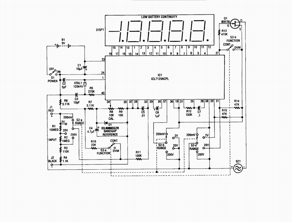
Single-chip digital voltmeter. This 4 1/2-digit DVM circuit is built around a Maxim ICL7129ACPL A/D converter and LCD driver. An ICL8069 CCZR 1.2-V band-gap reference diode is used for accuracy. The described circuit is a single-chip digital voltmeter (DVM) utilizing...
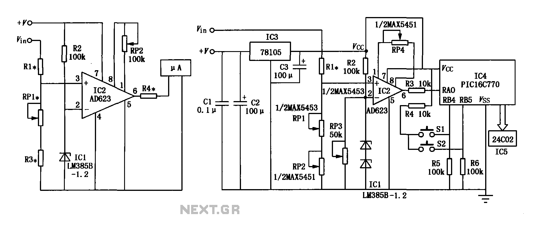
The range precision voltmeter electrical schematic is depicted in Figure (a) below. It features an amplifier circuit and several high-precision components that significantly enhance the performance range of the voltmeter. The inverting input of the instrumentation amplifier AD623 (IC2)...

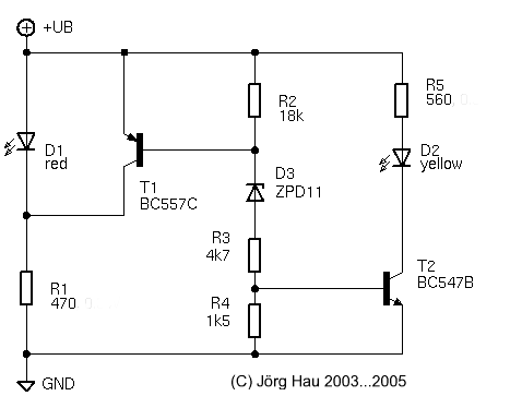
This is a low-power voltmeter circuit designed for use with alternative energy systems operating on 12V and 24V batteries. The voltmeter features an expanded scale that displays small voltage increments within the 10 to 16V range for 12V batteries...
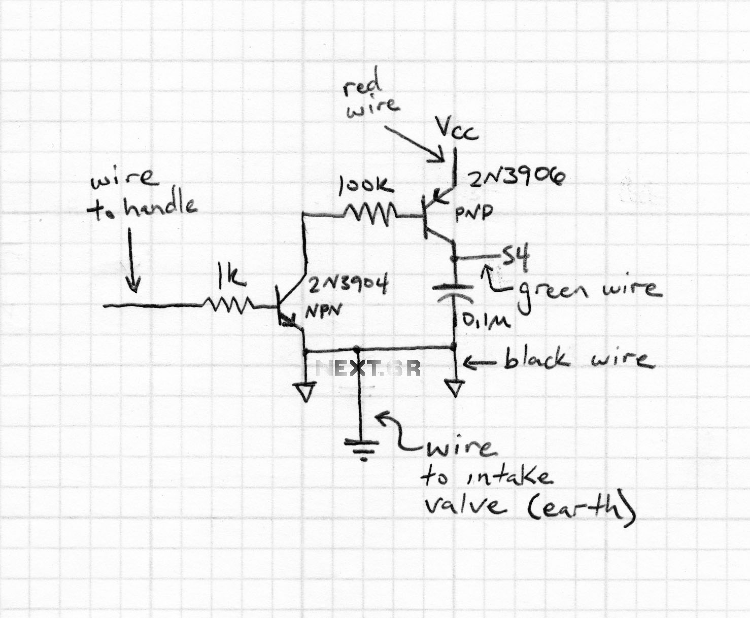
Typically, most Japanese motorcycles do not have a charge control lamp at all, and even on bikes equipped with such a lamp (like the Bosch system used in BMW and Moto Guzzi), defects may still occur, causing the "idiot...
The 1N4001 is a 1 Amp silicon rectifier with a voltage range of 50 to 1000 volts. It features guaranteed high-temperature soldering, high current capability, a diffused junction, low reverse leakage, and utilizes a void-free molded plastic technique for...