
Low-power FM transmitter circuit diagram 1000M range

No description available.
Related Circuits
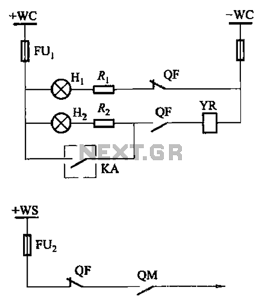
The CS2 type is a manually operated breaker mechanism commonly utilized for AC power operation and manual control signal circuits, as depicted in Figure 6-68. The circuit includes various components: wc for small signal bus control, QF for auxiliary...
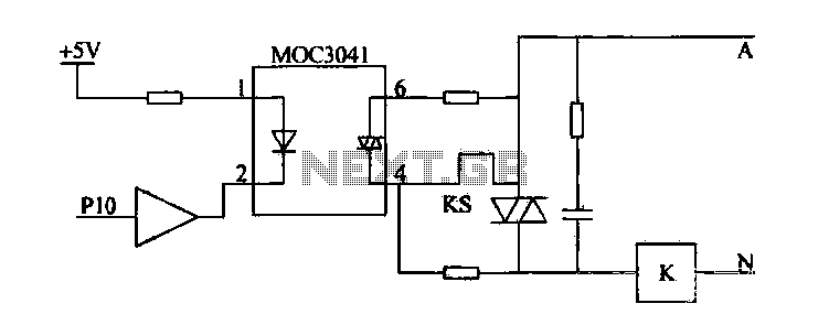
Device for an intermediate relay. The circuit utilizes a Triac AC contactor interface, employing the MOC3041 Triac output optical coupler to trigger the Triac. When Pl0 is low, the Triac will be activated, energizing the AC contactor coil. The described...
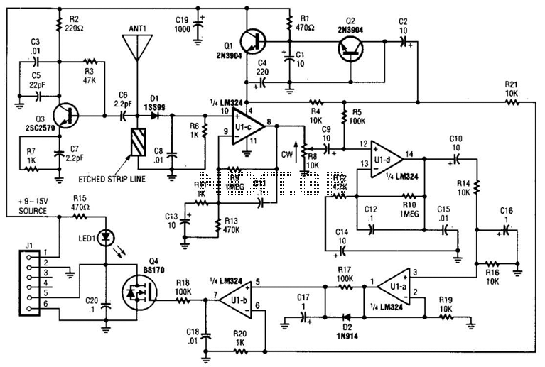
Operating at approximately 1.1 GHz, the detector senses disturbances in the electromagnetic field surrounding the antenna. The Doppler signal generated by detector D1 is amplified and used to control a power MOSFET switch. The antenna consists of a short...
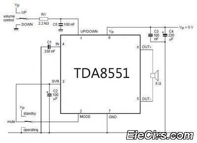
An amplifier with digital volume control can be designed predictably due to the simplicity of the circuit, which utilizes a single chip, the TDA8551. This series of mini amplifiers with digital volume control operates as a BTL (Bridge-Tied Load)...
DC Motor Control Using a Single Switch. This simple circuit allows for the operation of a DC motor in both clockwise and counterclockwise directions, as well as stopping it using a single switch. The circuit utilizes non-latching push button...
A simple soft start circuit is being developed that initially routes power through a resistor or thermistor before activating the main load. The soft start circuit is designed to gradually increase the power supplied to a load, thereby minimizing inrush...