
50 MHz converter
The described 50 MHz converter is designed to extend the coverage of general receivers, allowing for the reception of signals within the "Magic Band" frequency range of 50 MHz to 52 MHz. This frequency converter utilizes the Philips SA602 (or NE602/NE612) integrated circuit, which serves as a twice-balanced mixer oscillator. The SA602 is well-regarded for its low noise and power efficiency, making it suitable for a variety of communication applications, including VHF transceivers and RF data links.
The circuit typically consists of a few key components: the SA602 mixer, a local oscillator (LO), and a bandpass filter. The local oscillator generates a frequency that, when mixed with incoming RF signals, produces an intermediate frequency (IF) that falls within the range of the general coverage receiver. The choice of the LO frequency is critical, as it dictates the output frequency of the converter and can be adjusted to meet specific operational requirements.
In terms of performance, this converter is designed to be sensitive enough to pick up weak signals while maintaining a low noise figure, which is essential for clear signal reception, especially in crowded frequency environments. The stability of the circuit is enhanced through careful component selection and layout, ensuring that the converter can operate reliably over a range of temperatures and conditions.
The power consumption of the circuit is notably low, allowing it to be powered by standard voltage sources commonly found in portable and fixed installations. This makes it an attractive solution for hobbyists and professionals alike who require an efficient and effective means of expanding their receiver capabilities.
Overall, the 50 MHz converter represents a valuable addition to any general coverage receiver, enabling access to a unique segment of the radio spectrum with minimal investment in additional equipment.This is a very sensitive 50Mc converter allowing you to receive the entire "Magic Band" (50Mc...52Mc) on your general coverage receiver (28Mc...30Mc). It receives all types of modulated transmissions. It all depends on the receiver used. I`ve tested this project on a allmode Yaesu FRG-100 receiver. Within certain limits you can change the output frequency to suit your needs. The converter is very stable, low nois, sensitive and low on power consumption and can be compared to many commercial 50Mc receivers.
The heart of the converter has been built around Philips SA602 (NE602 or NE612), a twice balanced mixer oscillator. This IC finds his applications in layer capacity communication systems, cellular radio applications, RF data left, VHF-transceivers, broadb
🔗 External reference
Related Circuits
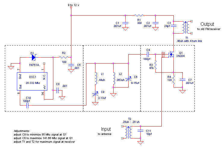
The FM broadcast band was moved immediately after World War II from its original spot just below 50 Mc to the present 88-108 Mc band. Hallicrafters was one company to offer receiving converters for those who had the old...
The circuit illustrated in the schematic diagram below is an isolated DC-to-DC step-up converter. The term "isolated" indicates that there is no electrical connection between the input and output sections of the circuit. The isolated DC-to-DC step-up converter operates by...
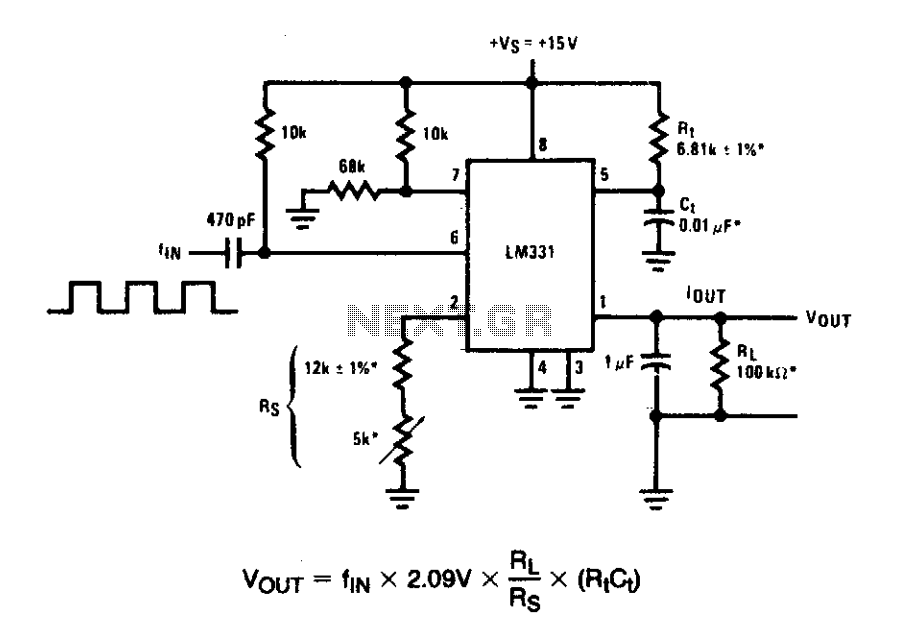
In these applications, a pulse input at a specified percentage is differentiated by a capacitor-resistor (C-R) network. The negative-going edge at pin 6 triggers the input comparator, activating the timer circuit. Similar to a voltage-to-frequency (V-to-F) converter, the average...
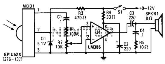
This circuit utilizes an infrared pulse-to-audio converter to assist in troubleshooting infrared remote controls, making it an effective tool for detecting infrared light sources. It employs a photo cell module (Radio Shack P/N 276-137) to detect IR radiation and...
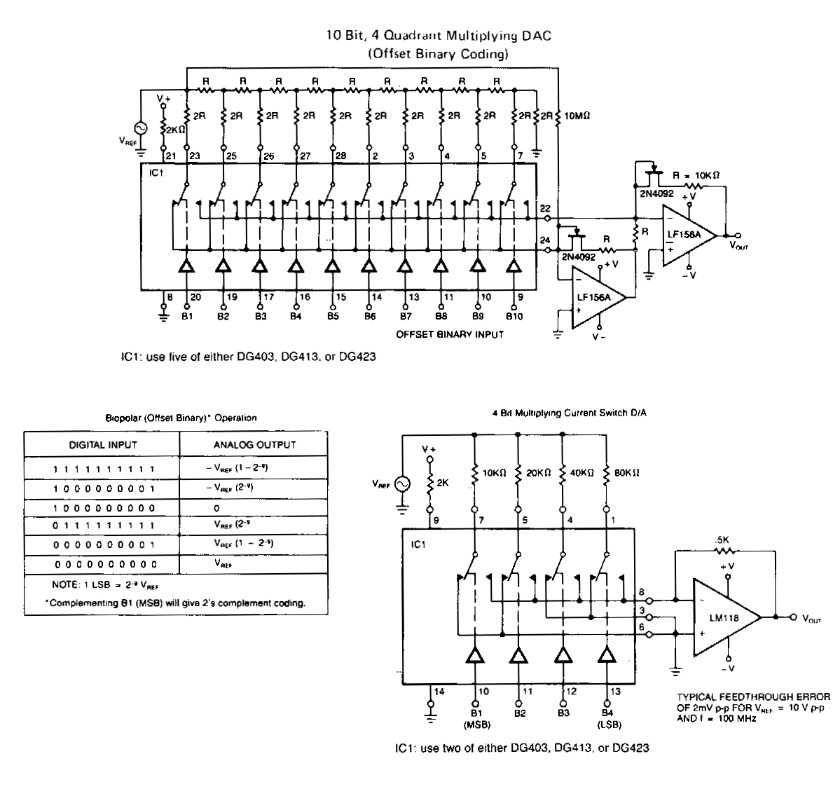
The following application circuits are designed to demonstrate several key concepts: A 2 kΩ resistor should be placed in series with the voltage source to limit supply current and mitigate negative ringing on the bit inputs. Temperature compensation for...
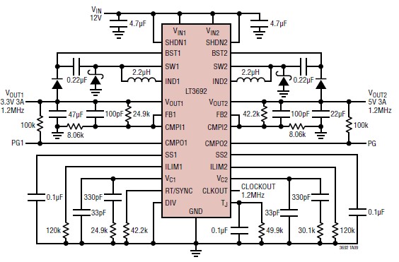
The LT3692 dual current mode PWM step-down DC-DC converter circuit, featuring two internal 3.5A switches, can be designed into a simple power supply circuit suitable for various electronic applications, such as distributed supply regulation or automotive circuits. The LT3692...