
LW, MW and SW bands Receiver

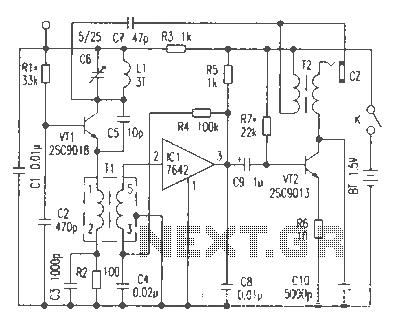
The described circuit is a compact regenerative receiver utilizing three transistors, designed to operate across a wide frequency range, particularly in the longwave (LW) and mediumwave (MW) bands. The architecture is influenced by the ZN414 integrated circuit, but this design significantly enhances coverage capabilities.
The circuit employs a fixed feedback mechanism to maintain stability and improve performance. This feedback is crucial as it allows the circuit to amplify weak signals effectively, providing good sensitivity and selectivity, especially in the LF (low frequency) and MW bands. The receiver is designed to operate without the need for an external antenna, which is a notable feature for compactness and ease of use. Instead, it utilizes a ferrite rod antenna, which can be salvaged from old portable radios. This rod is particularly effective for MW and LW reception, covering frequencies from approximately 540 kHz to 1600 kHz for MW and 140 kHz to 240 kHz for LW.
The fundamental operation of the receiver relies on a resonant circuit that captures electromagnetic signals at the tuned frequency. The circuit can be tuned to the desired frequency using variable capacitors or inductors, allowing for precise adjustments to optimize reception. The signal captured by the antenna is then amplified by the transistors, which are configured in a regenerative feedback loop. This loop not only amplifies the signal but also enhances the selectivity of the receiver, allowing it to distinguish between closely spaced frequencies.
In addition to the amplification stage, the receiver incorporates a rectification stage, typically using a crystal diode, such as galena or cat-whisker types. This stage converts the amplified radio frequency (RF) signal into an audio signal, making it suitable for listening. The simplicity of the design is an advantage, as it allows for straightforward construction and troubleshooting, making it accessible for both hobbyists and educational purposes.
Overall, this regenerative receiver design exemplifies a balance between simplicity and functionality, providing an effective solution for AM radio reception across a broad frequency spectrum without the complexities associated with more advanced receivers.This is a compact three transistor regenerative general coverage receiver with fixed feedback. It`s based on the principle of the ZN414 only much higher coverage. The sensitivity and selectivity is relative good (especially on the LF and MW bands) as can be expected with this "simple" design. The reception on the broadcast bands, LW(longwave) & MW(mediumwave) needs no external antenna! Just a ferrite rod which can be recovered from an old portable MW/LW radio which tuned from approximately 540 - 1600kHz on MW and 140kHz-240kHz for LW.
If you find such a radio you`ll wont need to make your own coils for those bands. An AM radio receiver is fundamentally a very simple device. In its simplest form, a resonant circuit builds up a signal if there is one in space at the frequency to which it is tuned. A crystal (galena and cat-whisker) then rectifies the signal, which rep 🔗 External reference
Related Circuits
This article discusses the functionality of a super-regenerative FM receiver. The principle behind this receiver utilizes high-gain miniature integrated circuits, resulting in a simple and innovative circuit design. It achieves the performance level of standard FM receivers while addressing...
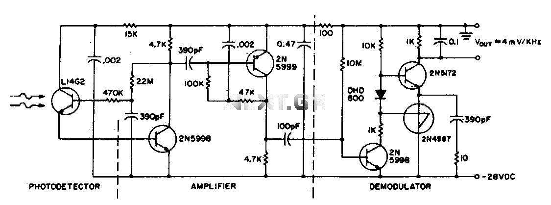
This circuit consists of an L14G2 detector, two stages of gain, and an FM demodulator. Better sensitivity can be obtained using more stages of stabilized gain with automatic gain control (AGC). The circuit design features an L14G2 detector, which serves...
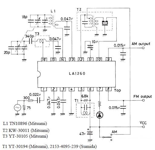
The FM IF MW radio receiver circuit schematic utilizes the LA1260 integrated circuit (IC) for AM and FM radio receiver electronic projects. The LA1260 incorporates numerous functions and features essential for radio receiver applications, including a high signal-to-noise ratio...
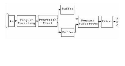
The barrier measurement method for distance is based on assessing the strength of a bound signal. A reflection wave is captured with an acceptor transducer, which emits a sine wave signal. The amplitude of this signal varies with the...
Various architectures of receivers have been proposed in literature, but the most popular architectures among them, such as Heterodyne, Homodyne, Wideband-IF, and Low-IF, are presented here. The Heterodyne receiver architecture utilizes two frequencies: the incoming radio frequency (RF) signal and...
An infrared (IR) transmitter-receiver system is being developed to send signals to a device, specifically a simple blue LED. The proposed infrared transmitter-receiver system consists of two main components: the IR transmitter and the IR receiver. The transmitter will emit...