
RGB To Monochrome converter

To effectively display color images on a black-and-white (B/W) or closed-circuit television (CCTV) monitor, it is essential to utilize a resistor network that combines the primary colors of red (R), green (G), and blue (B). The goal is to create a balanced signal that can be interpreted by the monochrome display without introducing ghosting effects.
The resistor network can be designed using three resistors, each connected to the output of the video card corresponding to the R, G, and B signals. The values of these resistors must be carefully chosen to ensure that the combined output does not exceed the input specifications of the monitor while maintaining the correct proportions of each color. A common configuration involves using equal resistor values, typically ranging from 1kΩ to 10kΩ, depending on the desired brightness and contrast levels.
To implement this circuit, the R, G, and B signals from the video card are fed into the resistor network. The output from the resistors is then connected to the composite input of the B/W or CCTV monitor. It is crucial to ensure that the video card is configured for a 60Hz interlaced output, as this refresh rate is optimal for reducing flicker and improving image stability on older monochrome displays.
In summary, by utilizing a simple resistor network to combine the RGB signals, it is possible to achieve a satisfactory display of color images on monochrome monitors, enhancing the viewing experience without the negative effects of ghosting. Proper configuration of the video card and careful selection of resistor values are key factors in the successful implementation of this solution.Often you can get away with running a monochrome monitor on GREEN, but this looks real crappy when viewing color images. These simple resistor networks allow you to display R+G+B on a B/W or CCTV monitor without ghosting. Be shure to set your video card for 60Hz interlaced. 🔗 External reference
Related Circuits
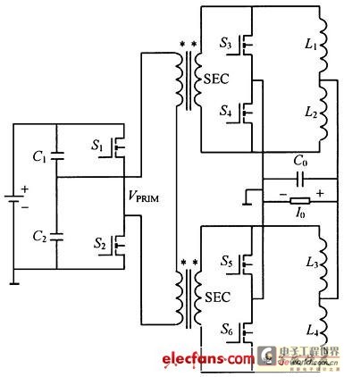
This structure significantly reduces electric current ripple on the filtering capacitance, thereby minimizing the inductive magnitude and overall size of the DC-DC converter. The converter operates at a switching frequency of 100 kHz with an input voltage of 48V....
Analog-to-digital converters (ADCs), printed-circuit board (PCB), microcontroller or digital signal processor (DSP), total-harmonic-distortion (THD), signal-to-noise ratio (SNR). Analog-to-digital converters (ADCs) are essential components in modern electronic systems, enabling the conversion of analog signals into digital form for processing by microcontrollers...
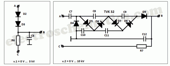
This high voltage converter circuit begins with a 30-volt power supply and is capable of delivering output voltages ranging from 0 to 3 kV for version 1, or from 0 to 10 kV for version 2. The high voltage converter...
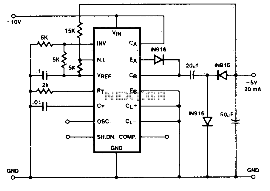
The capacitor-diode output circuit functions as a polarity converter, generating a -5 volt supply from a +15 volt input. This circuit can provide an output current of up to 20 mA without requiring additional boost transistors. The output transistors...
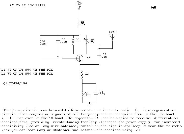
The circuit described is designed to enable the reception of AM stations on an FM radio. It operates as a regenerative circuit, sampling AM signals across various frequencies and retransmitting them within the FM band (88-108 MHz) and even...
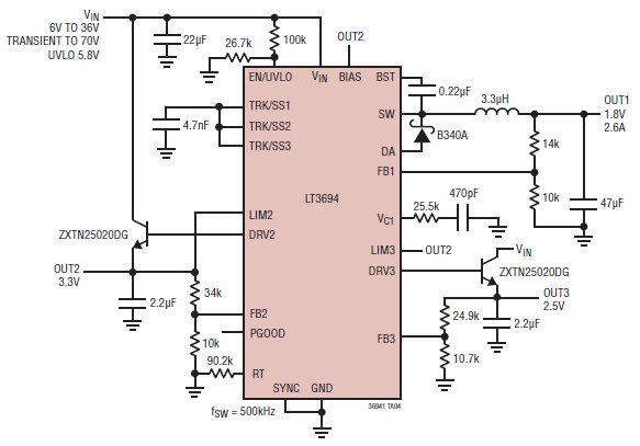
The LT3694 is a monolithic, current mode DC-DC converter that can be designed as a simple step-down converter, supporting a maximum output current of 2.6 A. This switching step-down converter is capable of generating up to 2.6 A at...