
Polarity converter

The capacitor-diode output circuit operates by utilizing a combination of capacitors and diodes to achieve voltage conversion. The primary component, a capacitor, is charged to the input voltage of +15 volts during one half of the AC cycle. When the polarity of the input changes, diodes are employed to discharge the capacitor, thus providing a negative voltage output of -5 volts.
In this configuration, the diodes serve to rectify the voltage, allowing current to flow in a controlled manner while preventing backflow. The output capacitor plays a crucial role in smoothing the output voltage, ensuring a stable -5 volt supply is delivered to the load. The design allows for an output current of up to 20 mA, making it suitable for various applications that require a negative voltage rail without the complexity of additional components such as boost transistors.
The current-limiting feature of the output transistors is essential for protecting the circuit from overcurrent conditions. This built-in protection mechanism ensures that the circuit operates within safe limits, thus enhancing reliability. The decision to exclude an inductor simplifies the design and reduces component count, which can be beneficial in applications where space and weight are critical factors.
Overall, this capacitor-diode output circuit is an efficient and straightforward solution for generating a negative voltage supply, leveraging the properties of capacitors and diodes to achieve the desired electrical characteristics while maintaining stability and safety.The capacitor-diode output circuit is used here as a polarity converter to generate a - 5 volt supply from +15 volts. This circuit is useful for an output current of up to 20 mA with no additional boost transistors required.
Since the output transistors are current limited, no additional protection is necessary Also, the lack of an inductor allows the circuit to be stabilized with only the output capacitor.
Related Circuits
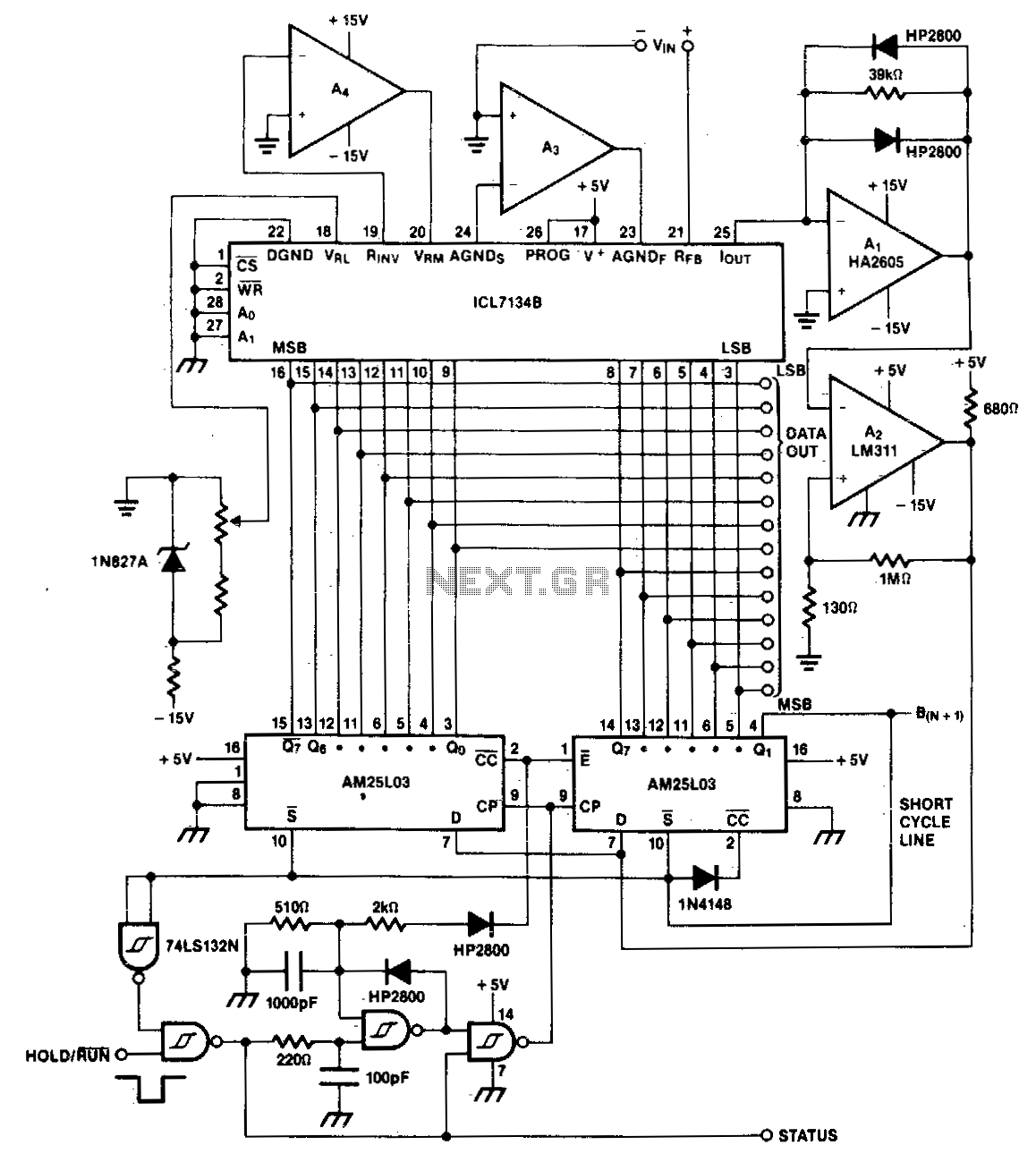
A bipolar input, high-speed A/D converter utilizes two AM25L03 devices to create a 14-bit successive approximation register. The comparator consists of a two-stage circuit featuring an HA2605 front-end amplifier, which is employed to minimize settling time issues at the...
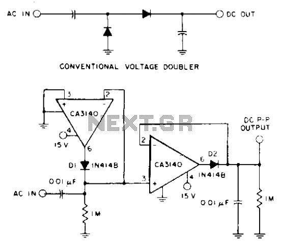
A CA3140 BiMOS operational amplifier, powered by a single positive supply, is employed to convert a traditional voltage doubler utilizing two precision diodes into a precise peak-to-peak AC-to-DC voltage converter. This configuration offers a wide dynamic range and extensive...
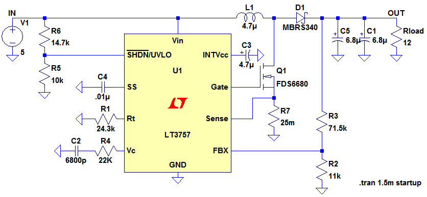
Ignore components C1, C2, R3. The MOSFET, Q1, switches on, creating a short circuit between the right-hand side of the inductor, L1, and ground (0V). A fixed voltage of 3.3V is applied across the inductor, causing its current to...
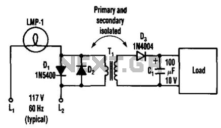
By connecting two back-to-back diodes in series with an AC power circuit, a voltage of approximately 1.4 Vpp can be achieved. This voltage is beneficial for energizing the primary coil of a small transformer. The voltage induced in the...
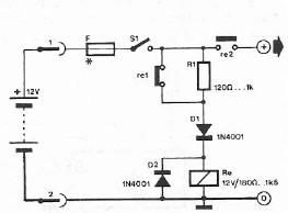
Safety polarity connection circuit design using common electronic components The safety polarity connection circuit is designed to ensure that electronic devices are connected with the correct polarity, preventing damage from reversed connections. This circuit typically employs common electronic components such...
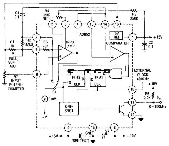
In this application, an AD652 integrated circuit (IC) is utilized in a synchronized voltage-to-frequency (V/F) converter that takes its input from the position of a potentiometer. This setup can represent the position of a mechanical component, weight, size, etc.,...