
Robot eyes

The circuit design incorporates a dual-eye obstacle detection system, employing infrared technology to enhance the robot's navigation capabilities. Each eye consists of an infrared LED paired with a phototransistor, enabling the detection of obstacles through reflected infrared light. The astable multivibrator functionality of the 556 timer IC (IC1-a) is crucial for generating a continuous square wave signal at approximately 1 kHz, which drives the infrared LEDs.
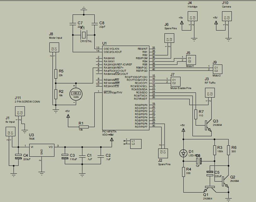
When an obstacle interrupts the path of the right eye, the reflected light is captured by the phototransistor Q2, which converts the light signal into an electrical signal. This signal is then amplified by transistor Q3, providing sufficient current to trigger the 555 timer IC (IC2). Operating in monostable mode, IC2 produces a pulse output that can be adjusted for duration based on the resistance value of R11, allowing for flexibility in response time. The output pulse energizes relay RY1, which alters the voltage polarity supplied to the motor, enabling the robot to change direction away from the detected obstacle.
The left eye mirrors this functionality, utilizing the second half of the 556 timer IC (IC1-b) to ensure synchronized operation. This dual-eye system enhances the robot's ability to navigate its environment autonomously, effectively avoiding obstacles through real-time detection and response. The design emphasizes reliability and efficiency, making it suitable for various robotic applications requiring obstacle avoidance.An infrared LED and a phototransistor are used for each eye. Half of a 556 timer IC (ICl-a) functions as an as table multivibrator oscillating at a frequency of about 1 kHz. That IC drives transistor Ql which in turn drives the two infrared LED's, LED1 and LED2. The right eye is composed of LED1 and Q2. If an obstacle appears in front of the right eye, pulses from LED1 are reflected by the obstacle and detected by Q2.
The signal from Q2 is amplified by Q3, which triggers IC2, a 555. That IC operates in the monostable mode, and it provides a pulse output with a width of as much as 2.75 seconds, depending on the setting of Rll. That pulse output energizes relay RY1, and that reverses the polarity of the voltage applied to the motor.
Corresponding portions of the circuit of the left eye operate in the same fashion, using the unused half of the 556 (ICl-b). That action causes the robot to turn away from an obstacle.
Related Circuits
The TINAH board shield is a printed circuit board designed for the Phys253 course, first utilized in 2009 by Engineering Physics students and faculty. This shield functions as a buffer to protect the digital and analog inputs and outputs...
The principles of DC motors are discussed in the beginner and intermediate sections of this tutorial. This section will address the electronics required to interface them with a Basic X microcontroller or other digital chips. The simplest method of...
This is the fifth iteration of a robot named Cruddy version 2. It functions as a line-following robot and features an improved circuit design, originally conceived by the designer. Notably, this project does not utilize a microcontroller; instead, it...
The headlights and photo cells are oriented downward, leading to the visualization of the entire circuit as being inverted. The configuration utilizes three LEDs on each side. This choice is likely due to the inability to power three LEDs...
The strategy focused on efficiently navigating complex terrain with superior speed. The objective was to score in the lowest scoring goal by acting quickly to limit the opposing team's points. The mechanical and electrical designs prioritized speed, resulting in...
The project is developed by Team Stark, with Gilbert as the leader and team members Martin and Janssen. The tasks have been divided into three parts. The first part includes camera control, login database, installer, and network setup, which...