
robot guts

The circuit described employs a straightforward yet effective design utilizing a pair of photo resistors (LDRs) and a dual voltage comparator IC. The orientation of the headlights and photo cells facing the ground suggests that the system is intended for ground detection or navigation based on light levels.
The use of three LEDs per side is strategic; it ensures that adequate brightness is achieved while managing the limitations of the 9V power supply. When connected in series, the forward voltage drop of each LED must be considered; therefore, the inclusion of transistors allows for the control of the LEDs without exceeding the supply voltage. The transistors act as switches, enabling or disabling the LEDs based on the comparator's output.
The NTE943M comparator plays a crucial role in the circuit's functionality. It compares the voltage levels from the two sets of photo resistors. When one set of LDRs detects more light, it generates a lower resistance, resulting in a higher voltage output. The comparator processes these signals and determines which set of LEDs should be activated. This feedback mechanism allows the robot to respond dynamically to changes in light conditions, effectively guiding its behavior based on environmental inputs.
In summary, this circuit exemplifies a robust design for light-sensitive applications, utilizing basic electronic components to achieve a functional and responsive system. The integration of the comparator and transistors ensures efficient operation while maintaining simplicity in the overall architecture.The headlights and photo cells will face the ground, so I find it easiest to imagine that the whole circuit is upside down Why 3 LEDs per side As far as I can tell, because you can`t power three in series from a single 9V battery without a little help, and this way Cook could include transistors in the circuit. The robot`s thinking is simple. The lone IC is an NTE943M low power, low offset, dual voltage comparator. It identifies which set of photo resistors is running at a higher voltage (a function of increased resistance, meaning which set is receiving less light), and lights the set of LEDs corresponding with the other set ” the set receiving more light. 🔗 External reference
Related Circuits
The individual has been engaged in garden railroading for just over a year, utilizing skills from various hobbies. They have designed and built two scratch-built bridges and nearly 100 trestle bents to support a 200-foot main line. Their interests...

This simple robot responds to light and avoids obstacles without the need for a microcontroller, programmer, or PC. The only specialized component in the circuit is a window discriminator, which functions as a window comparator. Resistors R1 and R2,...

This is a line follower designed to trace grid-type tracks. It features five line sensors for tracking the line. This arrangement of five sensors has proven effective, having been used multiple times with successful results. The device is named...
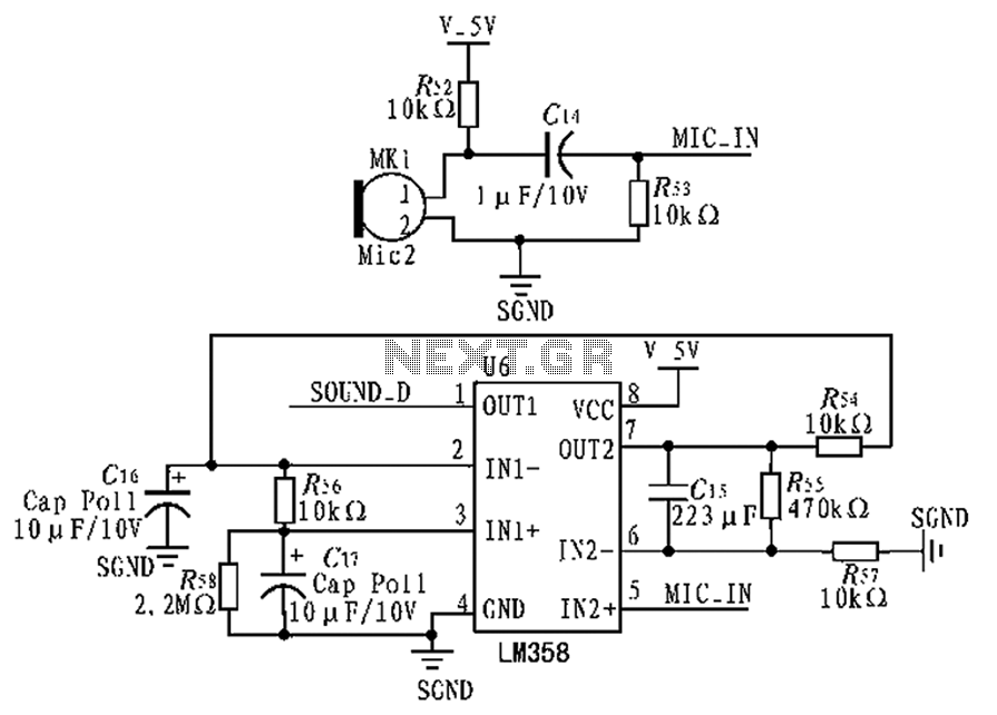
The circuit diagram focuses on the research and design features applied to mobile robots. The design considers small size, low power consumption, and ease of movement, catering to home users with a user-friendly display interface. For speech recognition, a...
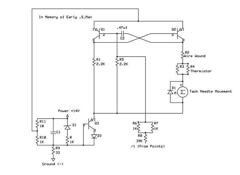
The "crossed-flags" topology of a monostable multivibrator is utilized in a 912 tachometer circuit. Resistor R5, which sets the discharge rate of capacitor C2, differs from that used in a 911 tachometer. The 912 configuration operates at a 50%...
The Automatic Forklift System (AFS) is engineered to enhance the safety and efficiency of warehouse stocking processes. Traditional manually operated forklifts pose injury risks to employees. The Automatic Forklift System (AFS) aims to mitigate these hazards. The Automatic Forklift System...