
Rolling Shutter Motor Control

The electrically operated rolling shutter system is designed to provide convenient control over the opening and closing of the shutter. The core component of this system is the control panel, which houses a three-position switch. This switch functions in three distinct modes: 'up' for raising the shutter, 'down' for lowering it, and 'stop' to halt the operation at any desired position.
In a typical schematic, the power supply is connected to the control panel, which is integrated with a motor responsible for the movement of the shutter. The motor is often a DC or AC type, depending on the application requirements. The control panel’s switch connects to a relay or a motor driver circuit that regulates the direction of the motor based on the switch position.
When the 'up' position is selected, the relay energizes the motor in one direction, allowing the shutter to ascend. Conversely, selecting the 'down' position reverses the motor's direction, enabling the shutter to descend. The 'stop' position interrupts the power supply to the motor, effectively pausing the shutter's movement.
In addition to the basic functionality, safety features such as limit switches may be incorporated into the design. These switches detect the fully opened or closed positions of the shutter, automatically cutting off power to the motor to prevent damage from over-travel.
For advanced applications, the system may also include remote control capabilities, integrating wireless communication modules such as RF or Wi-Fi, allowing for operation from a distance. Overall, the electrically operated rolling shutter system enhances convenience and security, making it suitable for residential and commercial applications.An electrically operated rolling shutter usually has a standard control panel with a three-position switch: up, down and stop. If you would like to automa.. 🔗 External reference
Related Circuits
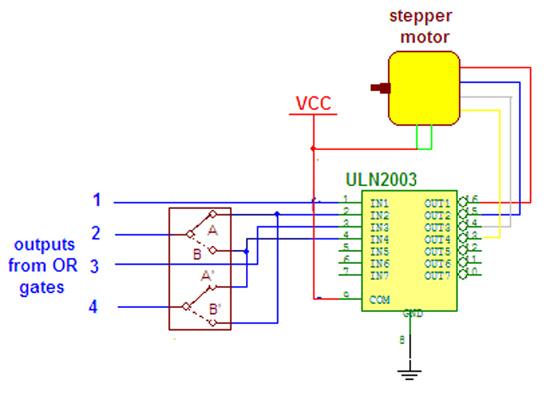
Wireless stepper motor speed control project using a laser and IC555. This project provides insights into the fundamentals and circuit construction for controlling the speed of a wireless stepper motor utilizing a laser and the IC 555 timer. The project...
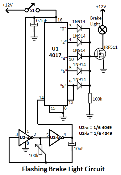
This flashing brake light circuit is designed for motorcycles. When the brake light switch S1 is closed, power is supplied to U1 and U2. The circuit utilizes two inverters from U2. The flashing brake light circuit operates by utilizing a...
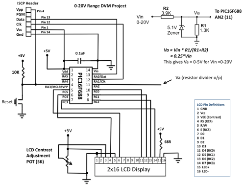
This project details the construction of a digital voltmeter utilizing a PIC microcontroller. A character-based HD44780 LCD display is employed to visualize voltage measurements. The microcontroller selected for this project is the PIC16F688, which features 12 I/O pins, with...
This circuit utilizes an MC3392 low-side protected switch in conjunction with an MC1455 timing circuit to create a dimmer control for automotive instrumentation panel lamps. The brightness of incandescent lamps is adjustable through Pulse Width Modulation (PWM) applied to...
A typical circuit for welding equipment is illustrated in the following circuit diagram. The turn-on delay can be accurately controlled with Potentiometer P2, allowing for effective discharge management. The welding equipment circuit typically incorporates several key components to ensure proper...
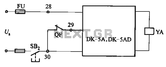
The DK-5A and DK-5AD AC power control circuit is illustrated in Figure 6-77. The figure includes a closing button (SBz) and a line (YA) connected to the closing electromagnet coil (U). This circuit is designed for the operation of...