
rotating flashing 230v lights

The circuit design incorporates a 230V/24V center-tapped transformer (T1) to step down the mains voltage to a lower level suitable for rectification. The full-wave rectifier composed of diodes D5 and D6 converts the AC voltage to DC, while the Zener diode D4 ensures that the output voltage does not exceed 15V, providing voltage regulation and protection for downstream components.
The use of triacs D7, D8, and D9 allows for the control of high-voltage loads, making the circuit versatile for various lighting applications. The optoisolators (IC2, IC3, IC4) provide electrical isolation between the control circuitry and the high-voltage components, ensuring safety and preventing interference.
The operational amplifiers configured as monostable multivibrators (IC1A, IC1B, IC1C) create a timed output pulse, which, when cascaded, generates a sequential activation of the triacs, producing a rotating light effect. This is particularly useful for decorative lighting applications where a dynamic display is desired.
The astable multivibrator (IC1D) is designed to generate a continuous square wave output, allowing for the simultaneous flashing of all connected lamp strings in the Flash mode. The adjustable nature of this configuration enables customization of the flash rate, catering to different aesthetic preferences.
The circuit's capability to drive multiple 230V lamps in parallel, while adhering to the maximum current specifications of the triacs, ensures flexibility in lighting design. The inclusion of trimmers R1, R2, and R3 allows for fine-tuning of the timing characteristics, facilitating the creation of visually appealing light patterns. The option to replace trimmers with fixed resistors provides an alternative for those seeking a simpler assembly with less variability in performance.
Overall, this circuit is well-suited for applications requiring both rotating and flashing light effects, making it ideal for festive decorations and other lighting displays.The 15V dc supply is obtained from a nominal 230/24V center tapped ac transformer (T1) and a full wave rectifier (D5 & D6): Zener diode D4 was added to clamp the dc voltage to 15V maximum. Triacs D7, D8 and D9 are insulated from the control circuitry by means of Optoisolators IC2, IC3 and IC4.
IC1A, B and C are wired as monostables and cascaded in order to obtain a rotating sequence when the Mode switch SW1 is set in the Rotate position. IC1D acts as an astable multivibrator and generates an adjustable flashlight, driving all three lamp strings at the same time when the Mode switch SW1 is set in the Flash position. Each channel can drive several 230V lamps wired in parallel for each string, provided the maximum current of the Triacs is not exceeded.
For example, each channel will be able to drive up to 20 40W bulbs. The circuit is also well suited for many small bulbs wired in series like the usual Christmas tree lamp strings decorations. As these are very low power devices, a lot of them can be driven by this circuit. The more lamps per string are used, the more satisfactory will be the resulting effect. The Trimmers R1, R2 and R3 should be adjusted to obtain equal delay times or until a pleasing visual result is obtained when observed from some distance.
In any case, the Trimmers can be substituted by three fixed 1/4W resistors of equal value: 100K, 220K or 470K will work fine. 🔗 External reference
Related Circuits

LEDs are rated for a continuous current of only 30 mA, while this circuit operates them at approximately 50 mA. Although this is acceptable for low duty cycles with short pulses, the intended design has a high duty cycle....

The Shenzhen Skywave Semiconductor Co., Ltd. produces a five-flash integrated circuit controller known as M1500P. This device is manufactured using a DIP 14 standard package and can be customized according to customer specifications for soft seal packaging. It operates...

A 2001 Chevrolet Cavalier has experienced a failure in one of the low beam headlights. Despite replacing the bulb, the headlight remains non-functional. Additionally, when the vehicle is shifted into gear, the daytime running lights flash multiple times before...

The circuit utilizes a 220V AC input, which is processed through a VD1-VD4 bridge rectifier to convert the AC voltage into a DC voltage. This DC voltage is then used to power eight lights labeled H1 to H8. Additionally,...
The circuit utilizes a 555 timer configured as a multivibrator, where the oscillation frequency is determined by resistors R1, R2, and capacitor C1. The frequency formula is given by fo = 1.443 / ((R1 + R2) * C1). The...
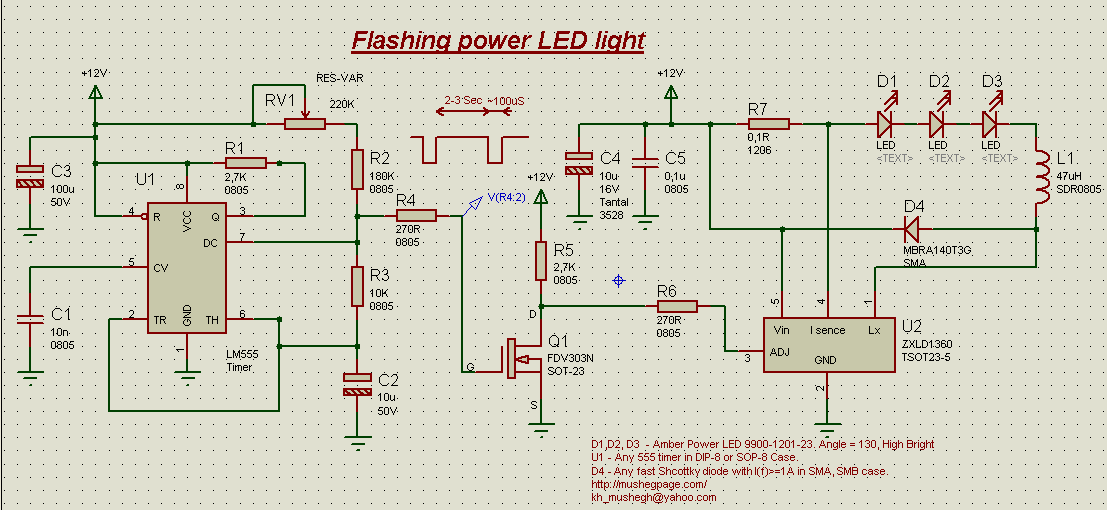
This project demonstrates the construction of a simple flashing light circuit using the IC 555 timer. The 555 timer functions as a clock generator with a duty cycle of less than 100% and greater than 50%. Additional components include...