
Rotative Speed Regulator Borer Driller Controller

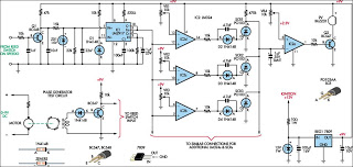
The rotary speed regulator circuit is designed to modulate the speed of electric motors commonly used in drilling and boring applications. The key components typically include a variable resistor, a transistor, and a microcontroller or a dedicated speed control IC, which collectively manage the voltage and current supplied to the motor.
In this circuit, the variable resistor allows the user to adjust the resistance, which in turn alters the voltage drop across the motor. This adjustment leads to a change in the speed of the motor's rotation. The transistor acts as a switch that can handle high current loads while being controlled by a low voltage signal from the microcontroller or speed control IC.
The microcontroller can be programmed to provide precise control over the motor speed, enabling features such as ramp-up and ramp-down speeds to prevent mechanical stress during operation. Feedback mechanisms, such as tachometers or encoders, may be integrated into the circuit to provide real-time speed monitoring and adjustments, ensuring optimal performance under varying load conditions.
Safety features, such as overcurrent protection and thermal shutdown, can also be incorporated to protect the circuit and the motor from damage during prolonged use or under heavy load conditions. The layout of the circuit should be designed to minimize noise and interference, ensuring stable operation and accurate speed regulation.
Overall, this rotary speed regulator circuit schematic represents an essential tool for enhancing the functionality and efficiency of drilling machines, providing users with the ability to tailor motor speed to specific applications and material requirements.This rotative speed regulator circuit schematic allows to control the holing speed of your borer or driller machine. This project is based on the fact tha.. 🔗 External reference
Related Circuits
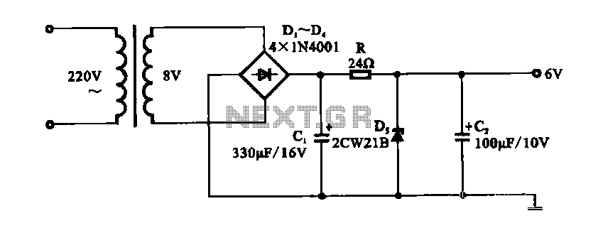
A DC shunt regulator power supply circuit is presented, which operates in parallel with a radio circuit. The circuit begins with an AC voltage of 22V, which is stepped down to 8V using a transformer. The 8V AC voltage...
This device is designed to be a simple, inexpensive comparator intended for use in a solar cell power supply setup where a quick "too low" or "just right" voltage indicator is needed. The circuit consists of one 5V regulator,...
This project shows you how to build a relay controller using the Basic Stamp I interfaced to the PC serial port. The Visual Basic 5 software developed for the interface lets you interact with the Basic Stamp to turn...
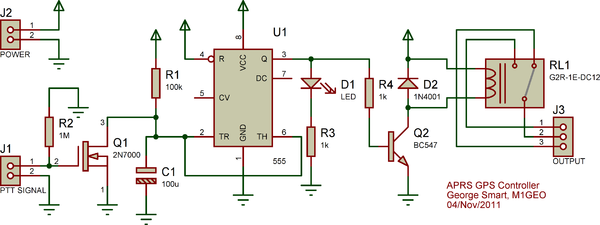
The Yaesu FT-7900E radio's power status can be utilized to manage the power status of the GPS and Tracker without requiring additional cabling. If implemented correctly, this would enable the radio's Auto-Power-Off feature to also turn off the GPS...
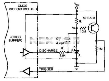
This circuit enables a microprocessor system to measure its own battery voltage. A Texas Instruments TI43 precision shunt regulator functions as a precise reference and integrator/amplifier, measuring its own supply through voltage-dependent charge and discharge time intervals. It is...
When driving, it can be difficult to gauge the speed of a vehicle, particularly on straight highways. If the vehicle exceeds a safe speed, it may lead to accidents. Therefore, a Car Speed Alarm circuit is necessary to alert...