
RS-232 to TTL cable with MAX232

The MAX232A is an integrated circuit specifically designed to facilitate the conversion of TTL (Transistor-Transistor Logic) levels to RS-232 levels, which are necessary for serial communication. The internal architecture of the MAX232A includes a double charge pump voltage doubler, which generates the necessary negative voltage from a single positive supply voltage, typically +5V. This is crucial for creating the RS-232 voltage levels, which range from +3V to +25V for a logical '1' and -3V to -25V for a logical '0'.
The voltage inverter within the MAX232A is engineered to generate both +10V and -10V outputs, ensuring that the device can produce the required signal levels for RS-232 communication. The charge pump operates by using capacitors to store and transfer charge, effectively doubling the input voltage and inverting it to create the negative voltage required for the RS-232 standard.
The MAX232A can support two separate serial ports, allowing for versatile applications in various electronic systems. However, it is common for users to connect only one port in many designs, which simplifies the circuit and reduces component count. The device is widely utilized in applications where serial communication is necessary, such as in microcontroller interfacing, data acquisition systems, and robotics.
For engineers and designers, the MAX232A offers a compact solution with minimal external components required, making it an efficient choice for implementing serial communication capabilities in embedded systems. The comprehensive data sheet provided by Maxim for the MAX232 and its variants includes detailed specifications, typical application circuits, and performance characteristics, serving as a valuable resource for design and implementation.Here is a diagram of the internals of the MAX232A. It shows a double charge pump voltage doubler and a +10v to -10v voltage inverter. The voltages output are used to generate the RS-232 compliant signals. The MAX232A has provisions for two serial ports on the same physical package. Most people only connect one of them. You can get a data sheet for the MAX232 and friends from Maxim. There are two camps on how to implement serial ports on a robot. One says stick the MAX232 on the robot. The other says don't. I kind of like the don't category! Most of my robots are autonomous, so I don't really need the MAX232 onboard consuming power. 🔗 External reference
Related Circuits
This web page outlines the installation and usage of ezlog data logging software. This software enables the measurement of the timing of various events, facilitating synchronization of different stimuli. Specifically, the software is designed to provide a detailed report...
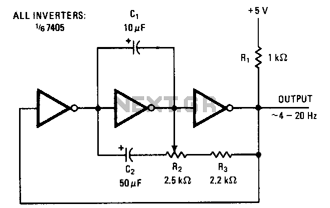
The symmetry of the square-wave output is maintained by connecting the right side of resistor R2 through resistor R3 to the output of the third amplifier stage. This configuration alters the charging current to the capacitors in proportion to...
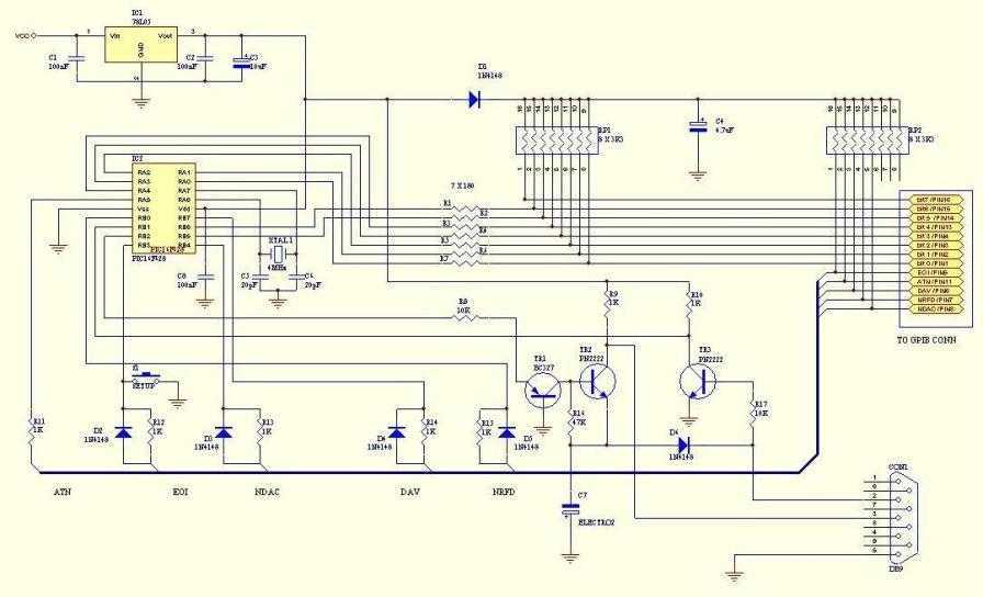
This adaptor will capture plots or prints of your GPIB instrument to your PC through the serial port. It fills the need of anybody who has a test instrument with the GPIB port and likes to get the screen...
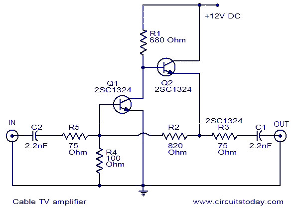
This is a simple cable TV amplifier using two transistors. The amplifier circuit is designed for cable TV systems utilizing 75 Ohm coaxial cables and is effective up to 150 MHz. Transistor T1 is responsible for amplification, providing up...
The most essential accessory for astrophotography, after a camera, telescope, and mount, is a remote shutter release to minimize vibration. A remote control is even more advantageous if it can trigger a series of exposures at preset intervals and...

RS-232 Serial Interface Status Indicator Circuit. This circuit utilizes a single logic integrated circuit (IC) to indicate the transmission (TXD) and reception (RXD) statuses of a serial interface. The RS-232 Serial Interface Status Indicator Circuit is designed to provide visual...