
Run-Down Clock/Sound Generator

The described circuit is a timing generator designed for applications in electronic roulette or dice games. It functions by generating a clock signal, which begins at a frequency in the range of several tens of kilohertz, contingent upon the capacitance value of capacitor C2. As the circuit operates, the clock frequency diminishes over a period of approximately 15 seconds. This gradual decrease in frequency is achieved through the discharge of capacitor C1 via resistor R4.
In terms of the circuit's operation, the clock signal is generated by a relaxation oscillator or a similar timing mechanism. The initial high frequency is determined by the charge and discharge characteristics of the capacitors involved, where C2 plays a pivotal role in establishing the starting frequency. As C1 discharges through R4, the voltage across it decreases, leading to a reduction in the clock signal frequency. This behavior can be utilized to create a suspenseful effect in games, where players anticipate the outcome as the frequency slows down.
Key components of the circuit include:
- C1: A capacitor that discharges over time, influencing the frequency of the clock signal.
- C2: A capacitor that sets the initial frequency of the oscillator.
- R4: A resistor that controls the discharge rate of C1, thereby affecting the time constant and the duration of the frequency decrease.
The design can be further enhanced by incorporating additional components such as transistors or logic gates to buffer the output signal, ensuring that it can drive other components in the game circuitry without significant signal degradation. Additionally, tuning elements such as variable resistors could be introduced to allow for adjustments in the timing characteristics, providing flexibility in game design. Overall, this circuit exemplifies a simple yet effective approach to generating a dynamic clock signal for interactive gaming applications. Used in electronic roulette or dice games, this circuit produces a clock signal that initially is several te ns of kHz (depending on C2) and gradually decreases to zero in about 15 seconds, as CI discharges through R4.
Related Circuits
This generator utilizes avalanche noise and is based on a design by Will Ware. It provides instructions for using a PIC chip to analyze a noise source and output random data serially. Circuit diagrams and links for fabricating a...
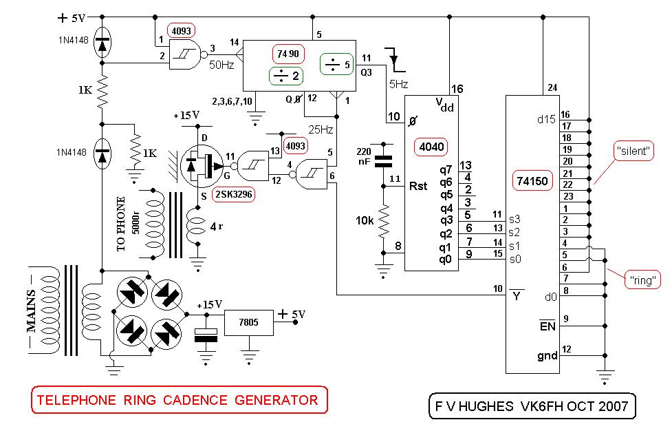
This design aims to restore the classic style of telephones that utilized a pair of gongs to signal an incoming call, evoking a sense of nostalgia with the familiar sound of ringing bells. Presented here is a "Telephone Ring...
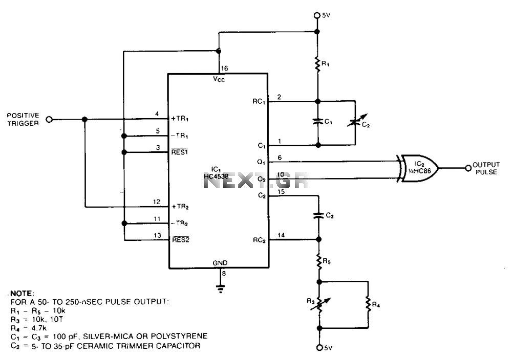
The pulse generator consists of two low-power CMOS chips that produce a precise pulse width ranging from 50 to 500 ns. IC1 is a dual monostable multivibrator (one shot) where each positive trigger pulse initiates simultaneous positive output pulses...
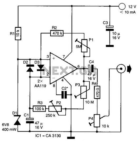
This circuit generates noise pulses suitable for test purposes. A Zener diode serves as the noise source. IC1 functions as a relaxation oscillator. P1 determines the noise bandwidth, while P2 and P3 control the noise amplification. The current consumption...
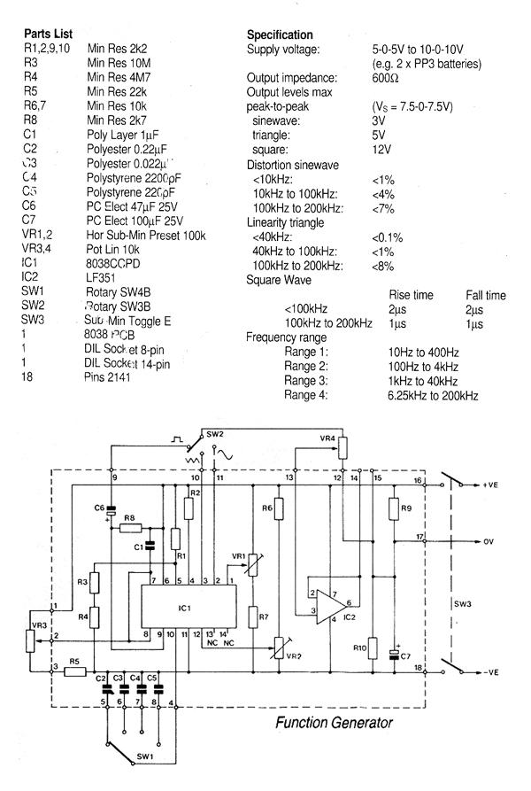
That circuit is based on a 14-pin DIL IC capable of producing sine, square, triangular, sawtooth, and pulse waveforms of high accuracy and stability. The frequency may be selected to be from 0.001Hz to 1MHz. Frequency modulation and sweeping...
This High Voltage power supply is able to generate up to 25-30kV DC Output from a 12-24v DC input. With a fully adjustable DC input power supply (0-24V/4A), it is possible to adjust the HV output between 5 to...